

page 400
13.2.2 Computer Control of Robot Paths (Incremental Interpolation)
•Path Planning is a simple process where the path planning methods described before (such as straight line motion) are used before the movement begins, and then a simple real-time lookup table is used.
•The path planner puts all of the values in a trajectory table.
•The on-line path controller will look up values from the trajectory table at predetermined time, and use these as setpoints for the controller.
•The effect of the two tier structure is that the robot is always shooting for the next closest ‘knot-point’ along the path.
page 401
|
|
Desired |
|
|
|
|
|
|
|
|
|
|
|
|
|
|
|
|
Set point |
|
||||
|
|
configuration |
|
|
|
|
|
|
Trajectory |
|
|
|
|
|||||||||||
|
|
|
|
|
|
Off-line |
|
|
Kinematic |
table |
|
|||||||||||||
Current |
|
|
|
|
||||||||||||||||||||
|
|
|
table |
|
||||||||||||||||||||
|
path |
|
|
|
|
|
|
|||||||||||||||||
|
|
|
Transforms |
|
|
|
|
|||||||||||||||||
Configuration |
|
|
|
|
|
|
|
|
|
|
|
|
|
|
||||||||||
|
planning |
|
|
|
|
|
|
|
|
|
|
|
|
|
||||||||||
|
|
|
|
|
|
|
|
|
|
|
|
|
|
|
|
|
||||||||
|
|
|
|
|
|
|
|
|
|
|
|
|
|
|
|
|
|
|
|
|
|
|||
|
|
|
|
|
|
|
|
|
|
|
|
|
|
|
|
|
|
|
|
|
|
|
|
|
|
|
|
|
|
|
|
|
|
|
|
|
|
Done before motion begins |
|
|
|
|
|||||||
|
|
|
|
|
|
|
|
|
|
|
|
|
|
|
|
|
||||||||
|
|
|
|
|
|
|
|
|
|
|
|
|
Done during motion, and all other times |
|
||||||||||
|
|
|
|
|
|
|
|
|
|
|
|
|
|
|||||||||||
|
|
|
|
|
|
|
|
|
|
|
|
|
||||||||||||
|
|
|
|
|
|
|
|
|
Time based interrupt |
Servo motor routine runs |
|
|||||||||||||
|
|
|
|
|
|
|
|
|
routine |
for each axis |
|
|
|
|
||||||||||
|
|
|
|
|
|
|
|
|
|
|
|
|
|
|
|
|
|
|
|
|
|
|
|
|
|
|
Interrupt |
|
|
|
|
|
|
|
Choose new |
|
|
|
|
|
|
|
|
||||||
|
|
|
|
|
|
|
|
|
|
|
|
|
|
|
|
|
||||||||
|
|
Clock |
|
|
|
|
|
|
|
|
|
|
|
|
|
|
|
|||||||
|
|
|
|
|
|
|
|
|
point from |
|
|
|
|
|
|
|
|
|||||||
|
|
|
|
|
|
|
|
|
|
|
|
|
|
|
|
|
|
|
||||||
|
|
|
|
|
|
|
|
|
|
|
trajectory table |
|
|
|
|
|
|
|
|
|||||
|
|
|
|
|
|
|
|
|
|
|
|
|
|
|
|
|
|
|
||||||
|
|
|
|
|
|
|
|
|
|
|
|
|
|
|
|
|
|
|||||||
|
|
|
|
|
|
|
|
|
|
|
|
|
|
|
|
|
|
|
Read θ desired |
|
|
|||
|
|
|
|
|
|
|
|
|
|
|
|
|
|
|
|
|
|
|
||||||
|
|
Set-point |
|
|
|
|
|
|
|
|
|
|
|
|
|
|
|
|
|
|
|
|
||
|
|
|
|
|
|
|
|
|
|
|
|
|
|
|
|
|
|
|
|
|
|
|||
|
|
|
|
|
|
|
|
|
|
|
|
|
|
|
|
|
|
|
|
|
|
|||
|
|
|
|
|
|
|
|
|
|
|
|
|
|
|
|
|
|
|
|
|
|
|||
|
|
table |
|
|
|
|
|
|
|
|
|
|
|
|
|
|
|
|
|
|
|
|
||
|
|
|
|
|
|
|
|
|
θ desired |
|
|
|
|
Compute |
|
|
|
|
||||||
|
|
|
|
|
|
|
|
|
|
|
|
|
|
|
|
|
|
|||||||
|
|
|
|
|
|
|
|
|
|
|
|
|
|
|
|
|
|
|
error |
|
|
|
|
|
|
|
|
|
|
|
|
|
|
|
|
|
|
|
|
|
|
|
|
|
|
|
|
|
|
|
|
|
|
|
|
|
|
|
|
|
|
|
|
|
|
|
|
|
|
|
|
|
|
|
|
|
|
|
|
|
|
|
|
|
|
|
|
|
|
|
|
|
|
|
|
|
|
|
|
|
|
Output actuator |
Return |
|
signal |
|
|
|
|
|
|
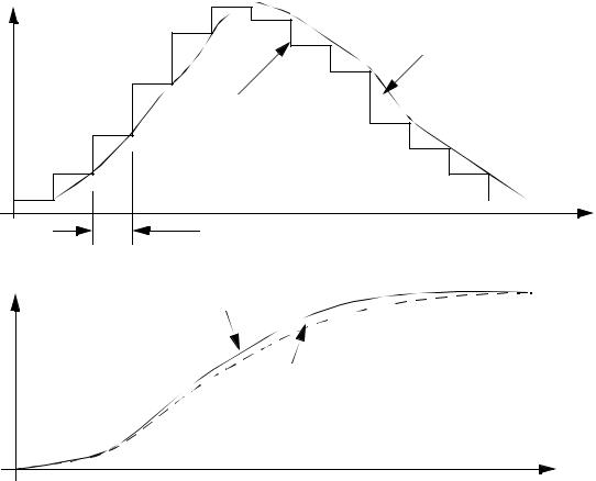
• The above scheme leads to errors between the planned, and actual path, and lurches occur
when the new setpoints are updated for each servo motor.
page 402
speed |
actual position |
trajectory table |
time |
trajectory table time step |
position
 required
 actual
time
•The quantization of the desired position requires a decision of what value to use, and this value is fixed for a finite time.
•The result is that the path will tend to look somewhat bumpy,