

eZ80® CPU User Manual
388
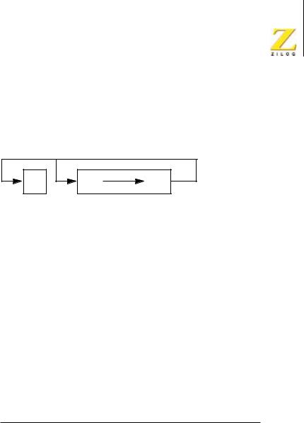
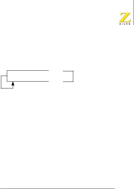
RRCA
Rotate Right with Carry–Accumulator
Operation
C |
7 |
0 |
A
Description
The CPU manipulates the contents of the accumulator, A, by rotating them right one bit position. The CPU next copies the contents of bit 0 into the Carry Flag and into bit 7.
Condition Bits Affected
S Not affected.
Z Not affected.
H Reset.
P/V Not affected.
N Reset.
C Data from bit 0 of the accumulator.
Attributes
Mnemonic |
Operand |
ADL Mode |
Cycle |
Op Code (hex) |
RRCA |
— |
X |
1 |
0F |
|
|
|
|
|
UM007712-0503 |
PRELIMINARY |
CPU Instruction Set |

eZ80® CPU User Manual
389
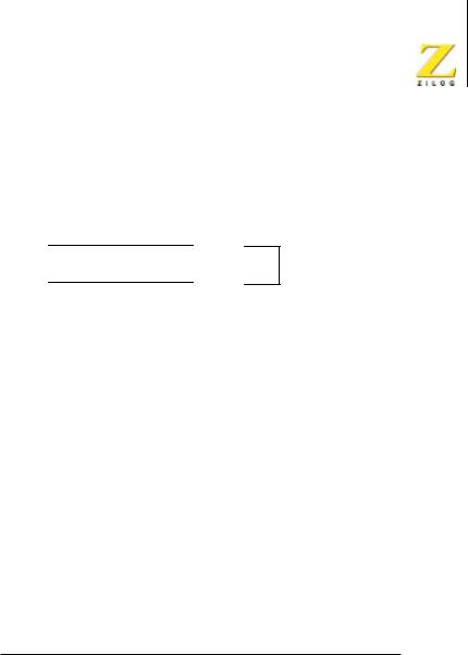
RRD
Rotate Right Decimal
Operation
|
|
|
|
|
|
|
|
|
|
|
|
|
|
|
|
|
|
|
|
|
|
|
|
|
|
A |
7 |
4 |
3 |
0 |
|
7 |
4 |
3 |
0 |
(HL) |
||
|
|
|
|
|
|
|
|
|
|
|
|
|
|
|
|
|
|
|
|
|
|
|
|
|
|
|
|
|
|
|
|
|
|
|
|
|
|
|
A[3:0] ← HL[3:0]
HL[7:4] ←A[3:0]
HL[3:0] ← HL[7:4]
Description
The CPU copies the contents of the low-order four bits of the memory location (HL) into the low-order four bits of the accumulator, A. The CPU next copies the previous contents of the low-order four bits of the accumulator into the high-order four bits of (HL). The CPU next copies the previous contents of the high-order four bits of (HL) into the low-order four bits of (HL).
Condition Bits Affected
S |
Set if the accumulator is negative; reset otherwise. |
Z |
Set if the accumulator is 0; reset otherwise. |
H |
Reset. |
P/V |
Set if parity of the accumulator is even; reset otherwise. |
N |
Reset. |
C |
Not affected. |
UM007712-0503 |
PRELIMINARY |
CPU Instruction Set |

eZ80® CPU User Manual
390
Attributes
Mnemonic |
Operand |
ADL Mode |
Cycle |
Op Code (hex) |
RRD |
— |
X |
5 |
ED, 67 |
|
|
|
|
|
UM007712-0503 |
PRELIMINARY |
CPU Instruction Set |

eZ80® CPU User Manual
391
RSMIX
Reset MIXED MEMORY Mode Flag
Operation
MADL ← 0
Description
The MIXED MEMORY Mode Flag (MADL) is reset to 0.
Condition Bits Affected
None.
Attributes
Mnemonic |
Operand |
ADL Mode |
Cycle |
Op Code (hex) |
RSMIX |
— |
X |
2 |
ED, 7E |
|
|
|
|
|
UM007712-0503 |
PRELIMINARY |
CPU Instruction Set |

eZ80® CPU User Manual
392
RST n
Restart
Operation
(SP) ← PC
PC ← {0000h,n}
Description
The RST instruction functions similar to a CALL instruction. However, the 8-bit n operand is limited to 8 specific values: 00h, 08h, 10h, 18h, 20h, 28h, 30h, and 38h. After stacking the Program Counter (and ADL mode bit, if necessary), the RST instruction is written the 8-bit restart vector n to the Program Counter.
Table 92. RST N Instruction Detail
ADL |
Suffix |
Operation |
0 |
None |
The starting Program Counter is {MBASE, PC[15:0]}. Push |
|
|
the 2-byte return address, PC[15:0], onto the {MBASE,SPS} |
|
|
stack. The ADL mode bit remains cleared to 0. Write {00h, |
|
|
nn} to PC[15:0]. The ending Program Counter is {MBASE, |
|
|
PC[15:0]}={MBASE, 00h, nn}. |
|
|
|
1 |
None |
The starting Program Counter is PC[23:0]. Push the 3-byte |
|
|
return address, PC[23:0], onto the SPL stack. The ADL mode |
|
|
bit remains set to 1. Write {0000h, nn} to PC[23:0]. The |
|
|
ending Program Counter is PC[23:0]={0000h, nn}. |
|
|
|
UM007712-0503 |
PRELIMINARY |
CPU Instruction Set |

eZ80® CPU User Manual
393
Table 92. RST N Instruction Detail
0 |
.S |
The starting Program Counter is {MBASE, PC[15:0]} Push |
|
|
the 2-byte return address, PC[15:0], onto the {MBASE, SPS} |
|
|
stack. Push a 02h byte onto the SPL stack, indicating an |
|
|
interrupt from Z80 mode (ADL=0). The ADL mode bit |
|
|
remains cleared to 0. Write {00h, nn} to PC[15:0]. The |
|
|
ending Program Counter is {MBASE, PC[15:0]}={MBASE, |
|
|
00h, nn}. |
|
|
|
1 |
.S |
The starting Program Counter is PC[23:0]. Push the 2 LS |
|
|
bytes of the return address, PC[15:0], onto the {MBASE, |
|
|
SPS} stack. Push the MS byte of the return address, |
|
|
PC[23:16], onto the SPL stack. Push a 03h byte onto the SPL |
|
|
stack, indicating an interrupt from ADL mode, because |
|
|
ADL=1. Reset ADL mode bit to 0. Write {00h, nn} to |
|
|
PC[15:0]. The ending Program Counter is {MBASE, |
|
|
PC[15:0]}={MBASE, 00h, nn}. |
|
|
|
0 |
.L |
The starting Program Counter is {MBASE, PC[15:0]}. Push |
|
|
the 2-byte return address, PC[15:0], onto the SPL stack. Push |
|
|
a 02h byte onto the SPL stack, indicating an interrupt from |
|
|
Z80 mode, because ADL=0. Set the ADL mode bit to 1. Write |
|
|
{0000h, nn} to PC[23:0]. The ending Program Counter is |
|
|
PC[23:0]={0000h, nn}. |
|
|
|
1 |
.L |
The starting Program Counter is PC[23:0]. Push the 3-byte |
|
|
return address, PC[23:0], onto the SPL stack. Push a 03h byte |
|
|
onto the SPL stack, indicating an interrupt from ADL mode, |
because ADL=1. The ADL mode bit remains set to 1. Write {0000h, nn} to PC[23:0]. The ending Program Counter is PC[23:0]={0000h, nn}.
Condition Bits Affected
None.
UM007712-0503 |
PRELIMINARY |
CPU Instruction Set |

eZ80® CPU User Manual
394
Attributes
Mnemonic |
Operand |
ADL Mode |
Cycle |
Op Code (hex) |
RST n |
n |
0/1 |
5/6 |
kk |
|
|
|
|
|
RST.S n |
n |
1 |
8 |
52, kk |
|
|
|
|
|
RST.L n |
n |
0 |
7 |
49, kk |
|
|
|
|
|
The Op Code (kk) is a function of the 8-bit Restart Address, n, and is assembled into one of the Op Codes indicated in Table 93.
Table 93. Restart Address and kk Op Codes for RST n Instruction (hex)
Restart |
|
Address |
kk |
|
|
00h |
C7 |
|
|
08h |
C |
|
|
10h |
D7 |
|
|
18h |
DF |
|
|
20h |
E7 |
|
|
28h |
EF |
|
|
30h |
F7 |
|
|
38h |
FF |
|
|
UM007712-0503 |
PRELIMINARY |
CPU Instruction Set |

eZ80® CPU User Manual
395
SBC A, (HL)
Subtract with Carry
Operation
A ←A–(HL)–C
Description
The (HL) operand is an 8-bit value at the memory location specified by the contents of the multibyte register (HL). This 8-bit value and the Carry Flag (C) are subtracted from the contents of the accumulator, A. The result is written to the accumulator.
Condition Bits Affected
S |
Set if result is negative; reset otherwise. |
Z |
Set if result is 0; reset otherwise. |
H |
Set if borrow from bit 4; reset otherwise. |
P/V |
Set if overflow; reset otherwise. |
N |
Set. |
C |
Set if borrow; reset otherwise. |
Attributes
Mnemonic |
Operand |
ADL Mode |
Cycle |
Op Code (hex) |
SBC |
A,(HL) |
X |
2 |
9E |
|
|
|
|
|
SBC.S |
A,(HL) |
1 |
3 |
52, 9E |
|
|
|
|
|
SBC.L |
A,(HL) |
0 |
3 |
49, 9E |
|
|
|
|
|
UM007712-0503 |
PRELIMINARY |
CPU Instruction Set |
eZ80® CPU User Manual
396
SBC A, ir
Subtract with Carry
Operation
A ←A–ir–C
Description
The rr operand is any of the 8-bit registers IXH, IXL, IYH, IYL. The ir operand and the Carry Flag (C) are subtracted from the contents of the accumulator, A. The result is written to the accumulator.
Condition Bits Affected
S |
Set if result is negative; reset otherwise. |
Z |
Set if result is 0; reset otherwise. |
H |
Set if borrow from bit 4; reset otherwise. |
P/V |
Set if overflow; reset otherwise. |
N |
Set. |
C |
Set if borrow; reset otherwise. |
Attributes
Mnemonic |
Operand |
ADL Mode |
Cycle |
Op Code (hex) |
|
SBC |
A,IXH |
X |
2 |
DD, 9C |
|
|
|
|
|
|
|
SBC |
A,IXL |
X |
2 |
DD, 9D |
|
|
|
|
|
|
|
SBC |
A,IYH |
X |
2 |
FD, |
9C |
|
|
|
|
|
|
SBC |
A,IYL |
X |
2 |
FD, |
9D |
|
|
|
|
|
|
UM007712-0503 |
PRELIMINARY |
CPU Instruction Set |

eZ80® CPU User Manual
397
SBC A, (IX/Y+d)
Subtract with Carry
Operation
A ←A–(IX/Y+d)–C
Description
The (IX/Y+d) operand is an 8-bit value at the memory location specified by the contents of the Index Register, IX or IY, added to the two’s-com- plement displacement d. This 8-bit value and the Carry Flag (C) are subtracted from the contents of the accumulator, A. The result is written to the accumulator.
Condition Bits Affected
S |
Set if result is negative; reset otherwise. |
Z |
Set if result is 0; reset otherwise. |
H |
Set if borrow from bit 4; reset otherwise. |
P/V |
Set if overflow; reset otherwise. |
N |
Set. |
C |
Set if borrow; reset otherwise. |
Attributes
Mnemonic |
Operand |
ADL Mode |
Cycle |
Op Code (hex) |
SBC |
A,(IX+d) |
X |
4 |
DD, 9E, dd |
|
|
|
|
|
SBC.S |
A,(IX+d) |
1 |
5 |
52, DD, 9E, dd |
|
|
|
|
|
SBC.L |
A,(IX+d) |
0 |
5 |
49, DD, 9E, dd |
|
|
|
|
|
SBC |
A,(IY+d) |
X |
4 |
FD, 9E, dd |
|
|
|
|
|
SBC.S |
A,(IY+d) |
1 |
5 |
52, FD, 9E, dd |
|
|
|
|
|
SBC.L |
A,(IY+d) |
0 |
5 |
49, FD, 9E, dd |
|
|
|
|
|
UM007712-0503 |
PRELIMINARY |
CPU Instruction Set |

eZ80® CPU User Manual
398
SBC A, n
Subtract with Carry
Operation
A ←A–n–C
Description
The 8-bit immediate value n and the Carry Flag (C) are subtracted from the contents of the accumulator, A. The result is written to the accumulator.
Condition Bits Affected
S |
Set if result is negative; reset otherwise. |
Z |
Set if result is 0; reset otherwise. |
H |
Set if borrow from bit 4; reset otherwise. |
P/V |
Set if overflow; reset otherwise. |
N |
Set. |
C |
Set if borrow; reset otherwise. |
Attributes
Mnemonic |
Operand |
ADL Mode |
Cycle |
Op Code (hex) |
SBC |
A,n |
X |
2 |
DE, nn |
|
|
|
|
|
UM007712-0503 |
PRELIMINARY |
CPU Instruction Set |

eZ80® CPU User Manual
399
SBC A, r
Subtract with Carry
Operation
A ←A–r–C
Description
The r operand is any of the 8-bit CPU registers A, B, C, D, E, H, or L. The r operand and the Carry Flag (C) are subtracted from the contents of the accumulator, A. The result is written to the accumulator.
Condition Bits Affected
S |
Set if result is negative; reset otherwise. |
Z |
Set if result is 0; reset otherwise. |
H |
Set if borrow from bit 4; reset otherwise. |
P/V |
Set if overflow; reset otherwise. |
N |
Set. |
C |
Set if borrow; reset otherwise. |
Attributes
Mnemonic |
Operand |
ADL Mode |
Cycle |
Op Code (hex) |
SBC |
A,r |
X |
1 |
jj |
|
|
|
|
|
jj identifies the A, B, C, D, E, H, or L register and is assembled into one of the Op Codes indicated in Table 94.
UM007712-0503 |
PRELIMINARY |
CPU Instruction Set |

eZ80® CPU User Manual
400
Table 94. Register and jj Op Codes for SBC A, r Instruction (hex)
Register |
jj |
|
|
A |
9F |
|
|
B |
98 |
|
|
C |
99 |
|
|
D |
9A |
|
|
E |
9B |
|
|
H |
9C |
|
|
L |
9D |
|
|
UM007712-0503 |
PRELIMINARY |
CPU Instruction Set |

eZ80® CPU User Manual
401
SBC HL, rr
Subtract with Carry
Operation
HL ← HL–rr–C
Description
The rr operand is any of the multibyte CPU registers BC, DE, or HL. The rr operand and the Carry Flag (C) are subtracted from the contents of the HL register. The result is written to HL.
Condition Bits Affected
S |
Set if result is negative; reset otherwise. |
Z |
Set if result is 0; reset otherwise. |
H |
Set if borrow from bit 12; reset otherwise. |
P/V |
Set if overflow; reset otherwise. |
N |
Set. |
C |
Set if borrow; reset otherwise. |
Attributes
Mnemonic |
Operand |
ADL Mode |
Cycle |
Op Code (hex) |
|
SBC |
HL,rr |
X |
2 |
ED, kk |
|
|
|
|
|
|
|
SBC.S |
HL,rr |
1 |
3 |
52, |
ED, kk |
|
|
|
|
|
|
SBC.L |
HL,rr |
0 |
3 |
49, |
ED, kk |
|
|
|
|
|
|
kk identifies either the BC, DE, HL, or SP multibyte register and is assembled into one of the Op Codes indicated in Table 95.
UM007712-0503 |
PRELIMINARY |
CPU Instruction Set |

eZ80® CPU User Manual
402
Table 95. Register and kk Op Codes for SBC HL, rr Instruction (hex)
Register kk
BC 42
DE 52
HL 62
UM007712-0503 |
PRELIMINARY |
CPU Instruction Set |

eZ80® CPU User Manual
403
SBC HL, SP
Subtract with Carry
Operation
HL ← HL–SP–C
Description
The Stack Pointer (SP) and the Carry Flag (C) are subtracted from the contents of the HL register. The result is written to HL. In ADL mode, or if the .L suffix is employed, the 24-bit Stack Pointer Long (SPL) is used. In Z80 mode of if the .S suffix is employed, the 16-bit Stack Pointer Short (SPS) is used.
Condition Bits Affected
S |
Set if result is negative; reset otherwise. |
Z |
Set if result is 0; reset otherwise. |
H |
Set if borrow from bit 12; reset otherwise. |
P/V |
Set if overflow; reset otherwise. |
N |
Set. |
C |
Set if borrow; reset otherwise. |
Attributes
Mnemonic |
Operand |
ADL Mode |
Cycle |
Op Code (hex) |
|
SBC |
HL,SP |
X |
2 |
ED, 72 |
|
|
|
|
|
|
|
SBC.S |
HL,SP |
1 |
3 |
52, |
ED, 72 |
|
|
|
|
|
|
SBC.L |
HL,SP |
0 |
3 |
49, |
ED, 72 |
|
|
|
|
|
|
UM007712-0503 |
PRELIMINARY |
CPU Instruction Set |

eZ80® CPU User Manual
404
SCF
Set Carry Flag
Operation
C ← 1
Description
The Carry Flag, C, is set to 1.
Condition Bits Affected
S Not affected.
Z Not affected.
H Reset.
P/V Not affected.
N Reset.
C Set.
Attributes
Mnemonic |
Operand |
ADL Mode |
Cycle |
Op Code (hex) |
SCF |
— |
X |
1 |
37 |
|
|
|
|
|
UM007712-0503 |
PRELIMINARY |
CPU Instruction Set |

eZ80® CPU User Manual
405
SET b, (HL)
Set Bit
Operation
(HL)[b] ← 1
Description
The (HL) operand is an 8-bit value at the memory location specified by the contents of the multibyte register (HL). Bit b of this 8-bit value is set to 1.
Condition Bits Affected
None.
Attributes
Mnemonic |
Operand |
ADL Mode |
Cycle |
Op Code (hex) |
|
SET |
b,(HL) |
X |
3 |
CB, kk |
|
|
|
|
|
|
|
SET.S |
b,(HL) |
1 |
4 |
52, |
CB, kk |
|
|
|
|
|
|
SET.L |
b,(HL) |
0 |
4 |
49, |
CB, kk |
|
|
|
|
|
|
kk=binary code 11 bbb 110; where bbb identifies the bit tested and assembled into the object code, as indicated in Table 96.
Table 96. bbb Op Codes for SET b, (HL) Instruction (hex)
Bit |
|
Tested |
bbb |
|
|
0 |
000 |
|
|
1 |
001 |
|
|
2 |
010 |
|
|
3 |
011 |
Bit |
|
Tested |
bbb |
|
|
4 |
100 |
|
|
5 |
101 |
|
|
6 |
110 |
|
|
7 |
111 |
UM007712-0503 |
PRELIMINARY |
CPU Instruction Set |
eZ80® CPU User Manual
406
SET b, (IX/Y+d)
Set Bit
Operation
(IX/Y+d)[b] ← 1
Description
The (IX/Y+d) operand is an 8-bit value at the memory location specified by the contents of the Index Register, IX or IY, added to the two’s-com- plement displacement d. Bit b this 8-bit value is set to 1.
Condition Bits Affected
None.
Attributes
Mnemonic |
Operand |
ADL Mode |
Cycle |
Op Code (hex) |
SET |
b,(IX+d) |
X |
5 |
DD, CB, dd, kk |
|
|
|
|
|
SET.S |
b,(IX+d) |
1 |
6 |
52, DD, CB, dd, kk |
|
|
|
|
|
SET.L |
b,(IX+d) |
0 |
6 |
49, DD, CB, dd, kk |
|
|
|
|
|
SET |
b,(IY+d) |
X |
5 |
FD, CB, dd, kk |
|
|
|
|
|
SET.S |
b,(IY+d) |
1 |
6 |
52, FD, CB, dd, kk |
|
|
|
|
|
SET.L |
b,(IY+d) |
0 |
6 |
49, FD, CB, dd, kk |
|
|
|
|
|
kk=binary code 11 bbb 110; where bbb identifies the bit tested and assembled into the object code, as indicated in Table 97.
UM007712-0503 |
PRELIMINARY |
CPU Instruction Set |

eZ80® CPU User Manual
407
Table 97. bbb Op Codes for SET b, (IX/Y+d) Instruction (hex)
Bit |
|
Tested |
bbb |
|
|
0 |
000 |
|
|
1 |
001 |
|
|
2 |
010 |
|
|
3 |
011 |
|
|
4 |
100 |
|
|
5 |
101 |
|
|
6 |
110 |
|
|
7 |
111 |
|
|
UM007712-0503 |
PRELIMINARY |
CPU Instruction Set |

eZ80® CPU User Manual
408
SET b, r
Set Bit
Operation
r[b] ← 1
Description
The r operand is any of the 8-bit CPU registers A, B, C, D, E, H, or L. Bit b of the specified register is set to 1.
Condition Bits Affected
None.
Attributes
Mnemonic |
Operand |
ADL Mode |
Cycle |
Op Code (hex) |
SET |
b,r |
X |
2 |
CB, jj |
|
|
|
|
|
jj=binary code 11 bbb rrr and kk=binary code 11 bbb 110; where rrr identifies the A, B, C, D, E, H, or L register and bbb identifies the bit tested and assembled into the object code, as indicated in Table 98.
Table 98. bbb, Register, and rrr Op Codes for SET b, r Instruction (hex)
Bit |
|
|
|
Tested |
bbb |
Register |
rrr |
|
|
|
|
0 |
000 |
A |
111 |
|
|
|
|
1 |
001 |
B |
000 |
|
|
|
|
2 |
010 |
C |
001 |
|
|
|
|
3 |
011 |
D |
010 |
|
|
|
|
UM007712-0503 |
PRELIMINARY |
CPU Instruction Set |

eZ80® CPU User Manual
409
Table 98. bbb, Register, and rrr Op Codes for SET b, r Instruction (hex)
Bit |
|
|
|
Tested |
bbb |
Register |
rrr |
|
|
|
|
4 |
100 |
E |
011 |
|
|
|
|
5 |
101 |
H |
100 |
|
|
|
|
6 |
110 |
L |
101 |
|
|
|
|
7 |
111 |
|
|
|
|
|
|
UM007712-0503 |
PRELIMINARY |
CPU Instruction Set |

eZ80® CPU User Manual
410
SLA (HL)
Shift Left Arithmetic
Operation
C |
7 |
0 |
0 |
|
|
(HL) |
|
Description
The (HL) operand is an 8-bit value at the memory location specified by the contents of the multibyte register (HL). The CPU manipulates the contents of this memory location, (HL), by shifting them left one bit position. The CPU next copies bit 7 into the Carry Flag and copies a 0 into bit 0 of the memory location, (HL).
Condition Bits Affected
S Set if result is negative; reset otherwise.
Z Set if result is 0; reset otherwise.
H Reset.
P/V Set if parity is even; reset otherwise.
N Reset.
C Data from bit 7 of the source.
Attributes
Mnemonic |
Operand |
ADL Mode |
Cycle |
Op Code (hex) |
|
SLA |
(HL) |
X |
5 |
CB, 26 |
|
|
|
|
|
|
|
SLA.S |
(HL) |
1 |
6 |
52, |
CB, 26 |
|
|
|
|
|
|
SLA.L |
(HL) |
0 |
6 |
49, |
CB, 26 |
|
|
|
|
|
|
UM007712-0503 |
PRELIMINARY |
CPU Instruction Set |
eZ80® CPU User Manual
411
SLA (IX/Y+d)
Shift Left Arithmetic
Operation
C |
7 |
0 |
0 |
|
|
(IX/Y+d) |
|
Description
The (IX/Y+d) operand is an 8-bit value at the memory location specified by the contents of the Index Register, IX or IY, added to the two’s-com- plement displacement d. The CPU manipulates the contents of this memory location, (IX/Y+d), by shifting them left one bit position. The CPU next copies bit 7 into the Carry Flag and copies a 0 into bit 0 of the memory location, (IX/Y+d).
Condition Bits Affected
S Set if result is negative; reset otherwise.
Z Set if result is 0; reset otherwise.
H Reset.
P/V Set if parity is even; reset otherwise.
N Reset.
C Data from bit 7 of the source.
UM007712-0503 |
PRELIMINARY |
CPU Instruction Set |

eZ80® CPU User Manual
412
Attributes
Mnemonic |
Operand |
ADL Mode |
Cycle |
Op Code (hex) |
SLA |
(IX+d) |
X |
7 |
DD, CB, dd, 26 |
|
|
|
|
|
SLA.S |
(IX+d) |
1 |
8 |
52, DD, CB, dd, 26 |
|
|
|
|
|
SLA.L |
(IX+d) |
0 |
8 |
49, DD, CB, dd, 26 |
|
|
|
|
|
SLA |
(IY+d) |
X |
7 |
FD, CB, dd, 26 |
|
|
|
|
|
SLA.S |
(IY+d) |
1 |
8 |
52, FD, CB, dd, 26 |
|
|
|
|
|
SLA.L |
(IY+d) |
0 |
8 |
49, FD, CB, dd, 26 |
|
|
|
|
|
UM007712-0503 |
PRELIMINARY |
CPU Instruction Set |
eZ80® CPU User Manual
413
SLA r
Shift Left Arithmetic
Operation
C |
7 |
0 |
0 |
|
|
r |
|
Description
The r operand is any of the 8-bit CPU registers A, B, C, D, E, H, or L. The CPU manipulates the contents of the r operand by shifting them left one bit position. The CPU next copies bit 7 into the Carry Flag and copies a 0 into bit 0 of the r operand.
Condition Bits Affected
S Set if result is negative; reset otherwise.
Z Set if result is 0; reset otherwise.
H Reset.
P/V Set if parity is even; reset otherwise.
N Reset.
C Data from bit 7 of the source.
Attributes
Mnemonic |
Operand |
ADL Mode |
Cycle |
Op Code (hex) |
SLA |
r |
X |
2 |
CB, jj |
|
|
|
|
|
jj identifies the A, B, C, D, E, H, or L register and is assembled into one of the Op Codes indicated in Table 99.
UM007712-0503 |
PRELIMINARY |
CPU Instruction Set |

eZ80® CPU User Manual
414
Table 99. Register and jj Op Codes for SLA r Instruction (hex)
Register |
jj |
|
|
A |
27 |
|
|
B |
20 |
|
|
C |
21 |
|
|
D |
22 |
|
|
E |
23 |
|
|
H |
24 |
|
|
L |
25 |
|
|
UM007712-0503 |
PRELIMINARY |
CPU Instruction Set |

eZ80® CPU User Manual
415
SLP
Sleep
Operation
This instruction places the CPU into SLEEP mode.
Description
SLEEP mode may not be supported on some eZ80® devices. Refer to the individual product specification for a detailed description.
Condition Bits Affected
None.
Attributes
Mnemonic |
Operand |
ADL Mode |
Cycle |
Op Code (hex) |
SLP |
— |
X |
2 |
ED, 76 |
|
|
|
|
|
UM007712-0503 |
PRELIMINARY |
CPU Instruction Set |
eZ80® CPU User Manual
416
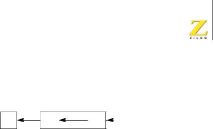
SRA (HL)
Shift Right Arithmetic
Operation
7  0
0 
 C (HL)
Description
The (HL) operand is an 8-bit value at the memory location specified by the contents of the multibyte register (HL). The CPU manipulates the contents of this memory location, (HL), by shifting them right one bit position. The CPU next copies the contents of bit 0 into the Carry Flag and leaves the previous contents of bit 7 unchanged.
Condition Bits Affected
S Set if result is negative; reset otherwise.
Z Set if result is 0; reset otherwise.
H Reset.
P/V Set if parity is even; reset otherwise.
N Reset.
C Data from bit 0 of the source.
Attributes
Mnemonic |
Operand |
ADL Mode |
Cycle |
Op Code (hex) |
|
SRA |
(HL) |
X |
5 |
CB, 2E |
|
|
|
|
|
|
|
SRA.S |
(HL) |
1 |
6 |
52, |
CB, 2E |
|
|
|
|
|
|
SRA.L |
(HL) |
0 |
6 |
49, |
CB, 2E |
|
|
|
|
|
|
UM007712-0503 |
PRELIMINARY |
CPU Instruction Set |
eZ80® CPU User Manual
417
SRA (IX/Y+d)
Shift Right Arithmetic
Operation
7  0
0 
 C (IX/Y+d)
Description
The (IX/Y+d) operand is an 8-bit value at the memory location specified by the contents of the Index Register, IX or IY, added to the two’s-com- plement displacement d. The CPU manipulates the contents of this memory location, (IX/Y+d), by shifting them right one bit position. The CPU next copies the contents of bit 0 into the Carry Flag and leaves the previous contents of bit 7 unchanged.
Condition Bits Affected
S Set if result is negative; reset otherwise.
Z Set if result is 0; reset otherwise.
H Reset.
P/V Set if parity is even; reset otherwise.
N Reset.
C Data from bit 0 of the source.
UM007712-0503 |
PRELIMINARY |
CPU Instruction Set |

eZ80® CPU User Manual
418
Attributes
Mnemonic |
Operand |
ADL Mode |
Cycle |
Op Code (hex) |
SRA |
(IX+d) |
X |
7 |
DD, CB, dd, 2E |
|
|
|
|
|
SRA.S |
(IX+d) |
1 |
8 |
52, DD, CB, dd, 2E |
|
|
|
|
|
SRA.L |
(IX+d) |
0 |
8 |
49, DD, CB, dd, 2E |
|
|
|
|
|
SRA |
(IY+d) |
X |
7 |
FD, CB, dd, 2E |
|
|
|
|
|
SRA.S |
(IY+d) |
1 |
8 |
52, FD, CB, dd, 2E |
|
|
|
|
|
SRA.L |
(IY+d) |
0 |
8 |
49, FD, CB, dd, 2E |
|
|
|
|
|
UM007712-0503 |
PRELIMINARY |
CPU Instruction Set |
eZ80® CPU User Manual
419
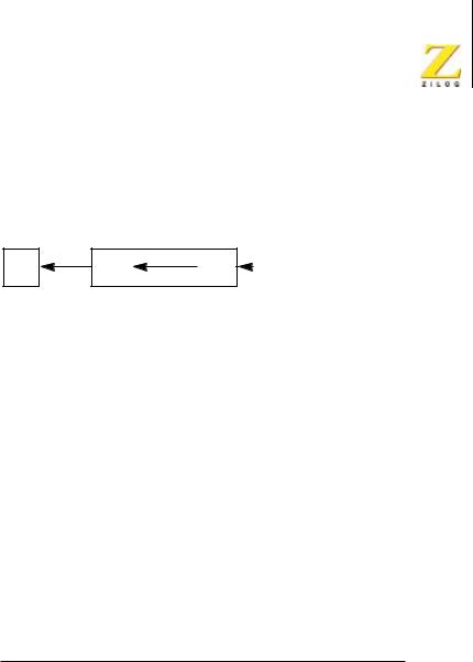
SRA r
Shift Right Arithmetic
Operation
7  0
0 
 C r
C r
Description
The r operand is any of the 8-bit CPU registers A, B, C, D, E, H, or L. The CPU manipulates the contents of the r operand by shifting them right one bit position. The CPU next copies the contents of bit 0 into the Carry Flag and leaves the previous contents of bit 7 unchanged.
Condition Bits Affected
S Set if result is negative; reset otherwise.
Z Set if result is 0; reset otherwise.
H Reset.
P/V Set if parity is even; reset otherwise.
N Reset.
C Data from bit 0 of the source.
Attributes
Mnemonic |
Operand |
ADL Mode |
Cycle |
Op Code (hex) |
SRA |
r |
X |
2 |
CB, jj |
|
|
|
|
|
jj identifies the A, B, C, D, E, H, or L register and is assembled into one of the Op Codes indicated in Table 100.
UM007712-0503 |
PRELIMINARY |
CPU Instruction Set |

eZ80® CPU User Manual
420
Table 100. Register and jj Op Codes for SRA r Instruction (hex)
Register |
jj |
|
|
A |
2F |
|
|
B |
28 |
|
|
C |
29 |
|
|
D |
2A |
|
|
E |
2B |
|
|
H |
2C |
|
|
L |
2D |
|
|
UM007712-0503 |
PRELIMINARY |
CPU Instruction Set |

eZ80® CPU User Manual
421
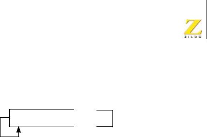
SRL (HL)
Shift Right Logical
Operation
0 
 7
7  0
0 
 C (HL)
Description
The (HL) operand is an 8-bit value at the memory location specified by the contents of the multibyte register (HL). The CPU manipulates the contents of this memory location, (HL), by shifting them right one bit position. The CPU next copies the contents of bit 0 into the Carry Flag and resets bit 7.
Condition Bits Affected
S Set if result is negative; reset otherwise.
Z Set if result is 0; reset otherwise.
H Reset.
P/V Set if parity is even; reset otherwise.
N Reset.
C Data from bit 0 of the source.
Attributes
Mnemonic |
Operand |
ADL Mode |
Cycle |
Op Code (hex) |
|
SRL |
(HL) |
X |
5 |
CB, 3E |
|
|
|
|
|
|
|
SRL.S |
(HL) |
1 |
6 |
52, |
CB, 3E |
|
|
|
|
|
|
SRL.L |
(HL) |
0 |
6 |
49, |
CB, 3E |
|
|
|
|
|
|
UM007712-0503 |
PRELIMINARY |
CPU Instruction Set |

eZ80® CPU User Manual
422
SRL (IX/Y+d)
Shift Right Logical
Operation
0 
 7
7  0
0 
 C (IX/Y+d)
Description
The (IX/Y+d) operand is an 8-bit value at the memory location specified by the contents of the Index Register, IX or IY, added to the two’s-com- plement displacement d. The CPU manipulates the contents of this memory location, (IX/Y+d), by shifting them right one bit position. The CPU next copies the contents of bit 0 into the Carry Flag and resets bit 7.
Condition Bits Affected
S Set if result is negative; reset otherwise.
Z Set if result is 0; reset otherwise.
H Reset.
P/V Set if parity is even; reset otherwise.
N Reset.
C Data from bit 0 of the source.
UM007712-0503 |
PRELIMINARY |
CPU Instruction Set |

eZ80® CPU User Manual
423
Attributes
Mnemonic |
Operand |
ADL Mode |
Cycle |
Op Code (hex) |
SRL |
(IX+d) |
X |
7 |
DD, CB, dd, 3E |
|
|
|
|
|
SRL.S |
(IX+d) |
1 |
8 |
52, DD, CB, dd, 3E |
|
|
|
|
|
SRL.L |
(IX+d) |
0 |
8 |
49, DD, CB, dd, 3E |
|
|
|
|
|
SRL |
(IY+d) |
X |
7 |
FD, CB, dd, 3E |
|
|
|
|
|
SRL.S |
(IY+d) |
1 |
8 |
52, FD, CB, dd, 3E |
|
|
|
|
|
SRL.L |
(IY+d) |
0 |
8 |
49, FD, CB, dd, 3E |
|
|
|
|
|
UM007712-0503 |
PRELIMINARY |
CPU Instruction Set |
eZ80® CPU User Manual
424
SRL r
Shift Right Logical
Operation
0 
 7
7  0
0 
 C r
C r
Description
The r operand is any of the 8-bit CPU registers A, B, C, D, E, H, or L. The CPU manipulates the contents of the r operand by shifting them right one bit position. The CPU next copies the contents of bit 0 into the Carry Flag and resets bit 7.
Condition Bits Affected
S Set if result is negative; reset otherwise.
Z Set if result is 0; reset otherwise.
H Reset.
P/V Set if parity is even; reset otherwise.
N Reset.
C Data from bit 0 of the source.
Attributes
Mnemonic |
Operand |
ADL Mode |
Cycle |
Op Code (hex) |
SRL |
r |
X |
2 |
CB, jj |
|
|
|
|
|
jj identifies the A, B, C, D, E, H, or L register and is assembled into one of the Op Codes indicated in Table 101.
UM007712-0503 |
PRELIMINARY |
CPU Instruction Set |

eZ80® CPU User Manual
425
Table 101. Register and jj Op Codes for SRL r Instruction (hex)
Register |
jj |
|
|
A |
3F |
|
|
B |
38 |
|
|
C |
39 |
|
|
D |
3A |
|
|
E |
3B |
|
|
H |
3C |
|
|
L |
3D |
|
|
UM007712-0503 |
PRELIMINARY |
CPU Instruction Set |