

eZ80® CPU User Manual
356
RETI
Return from Maskable Interrupt
Operation
PC ← (SP)
Description
The RETI instruction returns program control back to the point in the user’s application code where an interrupt caused the program control to jump to the current maskable interrupt service routine. The return address pops from the stack and is written to the Program Counter. Before the device executes the RETI instruction, the enable interrupt instruction (EI) should execute to allow recognition of interrupts after completion of the current interrupt service routine. The MADL control bit must be set to 1 to enable mixed-ADL mode interrupts. If the MADL is reset to 0, the suffixed instructions do not operate correctly. More detailed operation is provided in Table 86,
Table 86. RET Instruction Detail
ADL |
Suffix |
Operation |
0 |
None |
The starting Program Counter is {MBASE, PC[15:0]}. Pop a |
|
|
2-byte return address from {MBASE, SPS} into PC[15:0]. |
|
|
The ADL mode bit remains cleared to 0. The ending Program |
|
|
Counter is {MBASE, PC[15:0]}. |
|
|
|
1 |
None |
The starting Program Counter is PC[23:0]. Pop a 3-byte return |
|
|
address from SPL into PC[23:0]. The ADL mode bit remains |
|
|
set to 1. The ending Program Counter is PC[23:0]. |
|
|
|
UM007712-0503 |
PRELIMINARY |
CPU Instruction Set |

eZ80® CPU User Manual
357
Table 86. RET Instruction Detail
ADL |
Suffix |
Operation |
0 |
.S |
An invalid suffix. RETI.L must be used in all mixed-memory |
|
|
mode applications. |
|
|
|
1 |
.S |
An invalid suffix. RETI.L must be used in all mixed-memory |
|
|
mode applications. |
|
|
|
0 |
. L |
The MADL control bit must be set to 1 to enable mixed-ADL |
|
|
mode interrupts. The starting Program Counter is {MBASE, |
|
|
PC[15:0]}. Pop a byte from SPL into ADL to set the new |
|
|
memory mode (03h = ADL, 02h = Z80). |
|
|
If ADL mode { |
|
|
Pop the upper byte of the return address from SPL into |
|
|
PC[23:16]. Pop 2 LS bytes of the return address from |
|
|
{MBASE, SPS} into PC[15:0]. The ending Program |
|
|
Counter is PC[23:0] |
|
|
} |
|
|
else Z80 mode { |
|
|
Pop a 2-byte return address from {MBASE,SPS} into |
|
|
PC[15:0]. The ending Program Counter is {MBASE, |
|
|
PC[15:0]}. |
|
|
} |
|
|
|
1 |
.L |
The MADL control bit must be set to 1 to enable mixed-ADL |
|
|
mode interrupts. The starting Program Counter is PC[23:0]. |
Pop a byte from S2L into ADL to set the new memory mode (03h = ADL, 02h = Z80).
If ADL mode {
Pop 3-byte return address from SPL into PC[23:0]. The ending Program Counter is PC[23:0]
}
else Z80 mode {
Pop a 2-byte return address from SPL into PC[15:0]. The ending Program Counter is {MBASE, PC[15:0]}.
}
UM007712-0503 |
PRELIMINARY |
CPU Instruction Set |

eZ80® CPU User Manual
358
Condition Bits Affected
None.
Attributes
|
|
ADL |
|
|
Mnemonic |
Operand |
Mode |
Cycle |
Op Code (hex) |
|
|
|
|
|
RETI |
— |
0/1 |
6/7 |
ED, 4D |
|
|
|
|
|
RETI.L |
— |
0 |
8 if return to Z80 |
49, ED, 4D |
|
|
|
Mode, |
|
|
|
|
9 if return to ADL |
|
|
|
|
Mode |
|
|
|
|
|
|
RETI.L |
— |
1 |
8 if return to Z80 |
5B, ED, 4D |
|
|
|
Mode, |
|
|
|
|
9 if return to ADL |
|
|
|
|
Mode |
|
|
|
|
|
|
UM007712-0503 |
PRELIMINARY |
CPU Instruction Set |

eZ80® CPU User Manual
359
RETN
Return from Nonmaskable Interrupt
Operation
PC ← (SP)
IEF1 ← IEF2
Description
The RETN instruction returns program control back to the point in the user’s application code where an interrupt caused the program control to jump to the current nonmaskable interrupt service routine. The return address pops from the stack and is written to the Program Counter. The state of IEF2 is copied back into IEF1. As a result of this copy operation, maskable interrupts become immediately enabled following the RETN, but only if they were enabled before the nonmaskable interrupt occurred.
The MADL control bit must be set to 1 to enable mixed-ADL mode interrupts. If the MADL is reset to 0, the suffixed instructions do not operate correctly. More detailed operation is provided in Table 87.
Table 87. RETN Instruction Detail
ADL |
Suffix |
Operation |
0 |
None |
The starting Program Counter is {MBASE, PC[15:0]}. Pop a |
|
|
2-byte return address from {MBASE, SPS} into PC[15:0]. |
|
|
The ADL mode bit remains cleared to 0. The ending Program |
|
|
Counter is {MBASE, PC[15:0]}. |
|
|
|
1 |
None |
The starting Program Counter is PC[23:0]. Pop a 3-byte return |
|
|
address from SPL into PC[23:0]. The ADL mode bit remains |
|
|
set to 1. The ending Program Counter is PC[23:0]. |
|
|
|
0 |
.S |
An invalid suffix. RETN.L must be used in all mixed- |
|
|
memory mode applications. |
|
|
|
1 |
.S |
An invalid suffix. RETN.L must be used in all mixed- |
|
|
memory mode applications. |
|
|
|
UM007712-0503 |
PRELIMINARY |
CPU Instruction Set |

eZ80® CPU User Manual
360
Table 87. RETN Instruction Detail (Continued)
ADL |
Suffix |
Operation |
0 |
. L |
The MADL control bit must be set to 1 to enable mixed-ADL |
|
|
mode interrupts. The starting Program Counter is {MBASE, |
|
|
PC[15:0]}. Pop a byte from SPL into ADL to set the new |
|
|
memory mode (03h = ADL, 02h = Z80). |
|
|
if ADL mode { |
|
|
Pop the upper byte of the return address from SPL into |
|
|
PC[23:16]. |
|
|
Pop 2 LS bytes of the return address from {MBASE, SPS} |
|
|
into PC[15:0]. The ending Program Counter is PC[23:0] |
|
|
} |
|
|
else Z80 mode { |
|
|
Pop a 2-byte return address from {MBASE,SPS} into |
|
|
PC[15:0]. The ending Program Counter is {MBASE, |
|
|
PC[15:0]}. |
|
|
} |
|
|
|
1 |
.L |
The MADL control bit must be set to 1 to enable mixed-ADL |
|
|
mode interrupts The starting Program Counter is PC[23:0]. |
Pop a byte from SPL into ADL to set the new memory mode (03h = ADL, 02h = Z80).
if ADL mode {
Pop 3-byte return address from SPL into PC[23:0]. The ending Program Counter is PC[23:0]
}
else Z80 mode {
Pop a 2-byte return address from SPL into PC[15:0]. The ending Program Counter is {MBASE, PC[15:0]}.
}
Condition Bits Affected
None.
UM007712-0503 |
PRELIMINARY |
CPU Instruction Set |

eZ80® CPU User Manual
361
Attributes
|
|
ADL |
|
|
Mnemonic |
Operand |
Mode |
Cycle |
Op Code (hex) |
|
|
|
|
|
RETN |
— |
0/1 |
6/7 |
ED, 45 |
|
|
|
|
|
RETN.L |
— |
0 |
8 if return to Z80 |
49, ED, 45 |
|
|
|
Mode, |
|
|
|
|
9 if return to ADL |
|
|
|
|
Mode |
|
|
|
|
|
|
RETN.L |
— |
1 |
8 if return to Z80 |
5B, ED, 45 |
|
|
|
Mode, |
|
|
|
|
9 if return to ADL |
|
|
|
|
Mode |
|
|
|
|
|
|
UM007712-0503 |
PRELIMINARY |
CPU Instruction Set |
eZ80® CPU User Manual
362
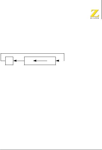
RL (HL)
Rotate Left
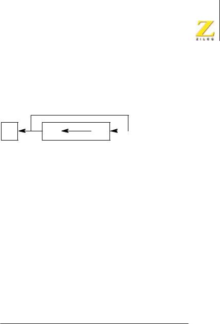
Operation
C |
7 |
0 |
(HL)
Description
The (HL) operand is an 8-bit value at the memory location specified by the contents of the multibyte register (HL). The CPU manipulates the contents of this memory location, (HL), by rotating them left one bit position. The CPU next copies bit 7 into the Carry Flag and copies the previous contents of the Carry Flag into bit 0 of the memory location, (HL).
Condition Bits Affected
S Set if result is negative; reset otherwise.
Z Set if result is 0; reset otherwise.
H Reset.
P/V Set if parity is even; reset otherwise.
N Reset.
C Data from bit 7 of the source.
Attributes
Mnemonic |
Operand |
ADL Mode |
Cycle |
Op Code (hex) |
|
RL |
(HL) |
X |
5 |
CB, 16 |
|
|
|
|
|
|
|
RL.S |
(HL) |
1 |
6 |
52, |
CB, 16 |
|
|
|
|
|
|
RL.L |
(HL) |
0 |
6 |
49, |
CB, 16 |
|
|
|
|
|
|
UM007712-0503 |
PRELIMINARY |
CPU Instruction Set |
eZ80® CPU User Manual
363
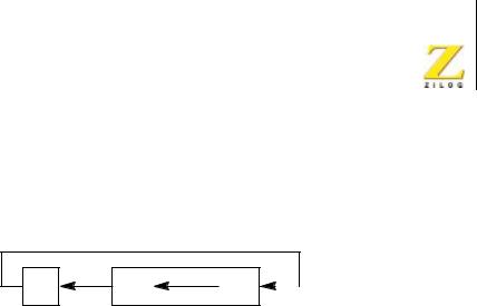
RL (IX/Y+d)
Rotate Left
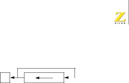
Operation
C |
7 |
0 |
(IX/Y+d)
Description
The (IX/Y+d) operand is an 8-bit value at the memory location specified by the contents of the Index Register, IX or IY, added to the two’s-com- plement displacement d. The CPU manipulates the contents of this memory location, (IX/Y+d), by rotating them left one bit position. The CPU next copies bit 7 into the Carry Flag and copies the previous contents of the Carry Flag into bit 0 of the memory location, (IX/Y+d).
Condition Bits Affected
S Set if result is negative; reset otherwise.
Z Set if result is 0; reset otherwise.
H Reset.
P/V Set if parity is even; reset otherwise.
N Reset.
C Data from bit 7 of the source.
UM007712-0503 |
PRELIMINARY |
CPU Instruction Set |

eZ80® CPU User Manual
364
Attributes
Mnemonic |
Operand |
ADL Mode |
Cycle |
Op Code (hex) |
RL |
(IX+d) |
X |
7 |
DD, CB, dd, 16 |
|
|
|
|
|
RL.S |
(IX+d) |
1 |
8 |
52, DD, CB, dd, 16 |
|
|
|
|
|
RL.L |
(IX+d) |
0 |
8 |
49, DD, CB, dd, 16 |
|
|
|
|
|
RL |
(IY+d) |
X |
7 |
FD, CB, dd, 16 |
|
|
|
|
|
RL.S |
(IY+d) |
1 |
8 |
52, FD, CB, dd, 16 |
|
|
|
|
|
RL.L |
(IY+d) |
0 |
8 |
49, FD, CB, dd, 16 |
|
|
|
|
|
UM007712-0503 |
PRELIMINARY |
CPU Instruction Set |
eZ80® CPU User Manual
365
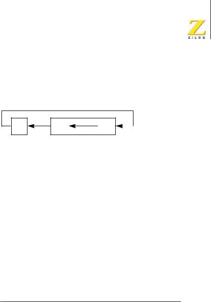
RL r
Rotate Left
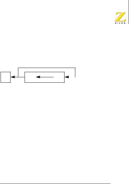
Operation
C |
7 |
0 |
r
Description
The r operand is any of the 8-bit CPU registers A, B, C, D, E, H, or L. The CPU manipulates the contents of the r operand by rotating them left one bit position. The CPU next copies bit 7 into the Carry Flag and copies the previous contents of the Carry Flag into bit 0 of the r operand.
Condition Bits Affected
S Set if result is negative; reset otherwise.
Z Set if result is 0; reset otherwise.
H Reset.
P/V Set if parity is even; reset otherwise.
N Reset.
C Data from bit 7 of the source.
Attributes
Mnemonic |
Operand |
ADL Mode |
Cycle |
Op Code (hex) |
RL |
r |
X |
2 |
CB, jj |
|
|
|
|
|
jj identifies the A, B, C, D, E, H, or L register and is assembled into one of the Op Codes indicated in Table 88.
UM007712-0503 |
PRELIMINARY |
CPU Instruction Set |
eZ80® CPU User Manual
366
Table 88. Register and jj Op Codes for RL r Instruction (hex)
Register |
jj |
|
|
A |
17 |
|
|
B |
10 |
|
|
C |
11 |
|
|
D |
12 |
|
|
E |
13 |
|
|
H |
14 |
|
|
L |
15 |
|
|
UM007712-0503 |
PRELIMINARY |
CPU Instruction Set |
eZ80® CPU User Manual
367
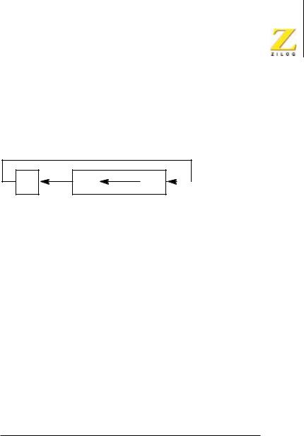
RLA
Rotate Left Accumulator
Operation
C |
7 |
0 |
A
Description
The CPU manipulates the contents of the accumulator, A, by rotating them left one bit position. The CPU next copies bit 7 into the Carry Flag and copies the previous contents of the Carry Flag into bit 0 of the m operand.
Condition Bits Affected
S Not affected.
Z Not affected.
H Reset.
P/V Not affected.
N Reset.
C Data from bit 7 of the accumulator.
Attributes
Mnemonic |
Operand |
ADL Mode |
Cycle |
Op Code (hex) |
RLA |
— |
X |
1 |
17 |
|
|
|
|
|
UM007712-0503 |
PRELIMINARY |
CPU Instruction Set |
eZ80® CPU User Manual
368
RLC (HL)
Rotate Left with Carry
Operation
C |
7 |
0 |
|
|
(HL) |
Description
The (HL) operand is an 8-bit value at the memory location specified by the contents of the multibyte register (HL). The CPU manipulates the contents of this memory location, (HL), by rotating them left one bit position. The CPU next copies bit 7 into the Carry Flag and into bit 0 of the memory location, (HL).
Condition Bits Affected
S Set if result is negative; reset otherwise.
Z Set if result is 0; reset otherwise.
H Reset.
P/V Set if parity is even; reset otherwise.
N Reset.
C Data from bit 7 of the source.
Attributes
Mnemonic |
Operand |
ADL Mode |
Cycle |
Op Code (hex) |
|
RLC |
(HL) |
X |
5 |
CB, 06 |
|
|
|
|
|
|
|
RLC.S |
(HL) |
1 |
6 |
52, |
CB, 06 |
|
|
|
|
|
|
RLC.L |
(HL) |
0 |
6 |
49, |
CB, 06 |
|
|
|
|
|
|
UM007712-0503 |
PRELIMINARY |
CPU Instruction Set |
eZ80® CPU User Manual
369
RLC (IX/Y+d)
Rotate Left with Carry
Operation
C |
7 |
0 |
|
|
(IX/Y+d) |
Description
The (IX/Y+d) operand is an 8-bit value at the memory location specified by the contents of the Index Register, IX or IY, added to the two’s-com- plement displacement d. The CPU manipulates the contents of this memory location, (IX/Y+d), by rotating them left one bit position. The CPU next copies bit 7 into the Carry Flag and into bit 0 of the memory location, (IX/Y+d).
Condition Bits Affected
S Set if result is negative; reset otherwise.
Z Set if result is 0; reset otherwise.
H Reset.
P/V Set if parity is even; reset otherwise.
N Reset.
C Data from bit 7 of the source.
UM007712-0503 |
PRELIMINARY |
CPU Instruction Set |

eZ80® CPU User Manual
370
Attributes
Mnemonic |
Operand |
ADL Mode |
Cycle |
Op Code (hex) |
RLC |
(IX+d) |
X |
7 |
DD, CB, dd, 06 |
|
|
|
|
|
RLC.S |
(IX+d) |
1 |
8 |
52, DD, CB, dd, 06 |
|
|
|
|
|
RLC.L |
(IX+d) |
0 |
8 |
49, DD, CB, dd, 06 |
|
|
|
|
|
RLC |
(IY+d) |
X |
7 |
FD, CB, dd, 06 |
|
|
|
|
|
RLC.S |
(IY+d) |
1 |
8 |
52, FD, CB, dd, 06 |
|
|
|
|
|
RLC.L |
(IY+d) |
0 |
8 |
49, FD, CB, dd, 06 |
|
|
|
|
|
UM007712-0503 |
PRELIMINARY |
CPU Instruction Set |
eZ80® CPU User Manual
371
RLC r
Rotate Left with Carry
Operation
C |
7 |
0 |
|
|
r |
Description
The r operand is any of the 8-bit CPU registers A, B, C, D, E, H, or L. The CPU manipulates the contents of the r operand by rotating them left one bit position. The CPU next copies bit 7 into the Carry Flag and into bit 0 of the r operand.
Condition Bits Affected
S Set if result is negative; reset otherwise.
Z Set if result is 0; reset otherwise.
H Reset.
P/V Set if parity is even; reset otherwise.
N Reset.
C Data from bit 7 of the source.
Attributes
Mnemonic |
Operand |
ADL Mode |
Cycle |
Op Code (hex) |
RLC |
r |
X |
2 |
CB, jj |
|
|
|
|
|
jj identifies the A, B, C, D, E, H, or L register and is assembled into one of the Op Codes indicated in Table 89.
UM007712-0503 |
PRELIMINARY |
CPU Instruction Set |

eZ80® CPU User Manual
372
Table 89. Register and jj Op Codes for RLC r Instruction (hex)
Register |
jj |
|
|
A |
07 |
|
|
B |
00 |
|
|
C |
01 |
|
|
D |
02 |
|
|
E |
03 |
|
|
H |
04 |
|
|
L |
05 |
|
|
UM007712-0503 |
PRELIMINARY |
CPU Instruction Set |