


Functional Overview
2.3PrimeCell KMI operation
The operation of the PrimeCell KMI is described in the following sections:
•Interface reset
•Clock signals
•Keyboard clock and data signals on page 2-8
•Keyboard/mouse data output on page 2-9
•Keyboard data input on page 2-9
•Timing requirements on page 2-11.
2.3.1Interface reset
The PrimeCell KMI is reset by the global reset signal BnRES and a block-specific reset signal nKMIRST. An external reset controller must use BnRES to assert nKMIRST asynchronously and negate it synchronously to KMICLK. BnRES should be asserted LOW for a period long enough to reset the slowest block in the on-chip system, and then taken HIGH again. The PrimeCell KMI requires BnRES to be asserted LOW for at least one period of PCLK.
The values of the registers after reset are detailed in Chapter 3 Programmer’s Model.
2.3.2Clock signals
The frequency of the clock signal KMIREFCLK should be selected to generate an internal nominal 8MHz clock signal.
The internal 8MHz clock signal is used for internal timing of signals, such as the keyboard request-to-send signal which is timed from 512 cycles of the internal 8MHz clock.
The 8MHz clock signal must have a minimum period of 117.2ns (that is, a maximum
frequency of 8.533MHz) in order to ensure that the request-to-send command is greater than 60.0μs.
The 8MHz clock signal must have a maximum period of 166.7ns (that is, a minimum
frequency of 6.0MHz) in order to ensure the correct sampling of keyboard clock signals as low as 1μs.
A nominal 8.0MHz internal clock signal (125ns period) will generate a typical request- to-send pulse width of 64μs.
Refer to Table 2-3 on page 2-12 for keyboard interface timing values.
2-6 |
© Copyright ARM Limited 1999. All rights reserved. |
DDI 0143C |
Functional Overview
The internal 8MHz clock is generated by dividing down from KMIREFCLK input clock. The divide value is programmed by writing to the KMICLKDIV register. A suitable KMIREFCLK frequency and divide value must be chosen to meet the constraints given below:
•F KMIREFCLK <= (1 + KMICLKDIV) * 8.533MHz
•F KMIREFCLK > (1 + KMICLKDIV) * 6.0MHz
An example table of divide values and KMIREFCLK frequency limits is shown in Table 2-1.
Table 2-1 Divide values and frequency limits
KMICLKDIV |
KMIREFCLK |
KMIREFCLK frequency (MHz) |
||
|
|
|
||
value |
divided by |
Min |
Typ |
Max |
|
|
|||
|
|
|
|
|
0 |
1 |
6.0 |
8.0 |
8.533 |
|
|
|
|
|
1 |
2 |
12.0 |
16.0 |
17.067 |
|
|
|
|
|
2 |
3 |
18.0 |
24.0 |
25.600 |
|
|
|
|
|
3 |
4 |
24.0 |
32.0 |
34.133 |
|
|
|
|
|
4 |
5 |
30.0 |
40.0 |
42.667 |
|
|
|
|
|
5 |
6 |
36.0 |
48.0 |
51.200 |
|
|
|
|
|
6 |
7 |
42.0 |
56.0 |
59.733 |
|
|
|
|
|
7 |
8 |
48.0 |
64.0 |
68.267 |
|
|
|
|
|
8 |
9 |
54.0 |
72.0 |
76.800 |
|
|
|
|
|
9 |
10 |
60.0 |
80.0 |
85.333 |
|
|
|
|
|
10 |
11 |
66.0 |
88.0 |
93.867 |
|
|
|
|
|
11 |
12 |
72.0 |
96.0 |
102.400 |
|
|
|
|
|
12 |
13 |
78.0 |
104.0 |
110.930 |
|
|
|
|
|
13 |
14 |
84.0 |
112.0 |
119.470 |
|
|
|
|
|
14 |
15 |
90.0 |
120.0 |
128.000 |
|
|
|
|
|
15 |
16 |
96.0 |
128.0 |
136.530 |
|
|
|
|
|
DDI 0143C |
© Copyright ARM Limited 1999. All rights reserved. |
2-7 |
Functional Overview
2.3.3Keyboard clock and data signals
The keyboard/mouse peripheral and PrimeCell KMI communicate using the clock and data signals. The sources of these signals are open-drain outputs with pull-up resistors, allowing either the peripheral or the PrimeCell KMI to force these lines LOW. When no communication is occurring, both clock and data are HIGH.
Data values are transmitted and received as a serial 11-bit data frame, which is illustrated in Figure 2-2.
Start bit |
|
|
|
|
|
|
Odd parity bit |
LSB |
|
|
|
|
|
|
MSB |
0 |
1 |
2 |
3 |
4 |
5 |
6 |
7 |
|
|
|
8 data bits |
|
|
Stop bit |
|
Figure 2-2 Serial data frame
The parity bit is used for error checking. An odd parity scheme is implemented such that:
•if an even number of data bits is set to 1 then the parity bit is asserted HIGH
•if an odd number of data bits is set to 1 is odd then the parity bit is LOW.
When the PrimeCell KMI transmits data to the keyboard/mouse peripheral, the PrimeCell KMI forces the data line to a LOW level, and allows the clock to go HIGH.
When the keyboard/mouse peripheral transmits or receives data from the PrimeCell KMI, it generates the clock signal to transfer the data. The PrimeCell KMI can prevent the keyboard/mouse peripheral from sending data by forcing the clock to a LOW level. At this time the data line can be either HIGH or LOW.
2-8 |
© Copyright ARM Limited 1999. All rights reserved. |
DDI 0143C |

Functional Overview
Line status indicated by keyboard clock and data signals is shown in Table 2-2.
|
|
Table 2-2 Line status |
|
|
|
Clock |
Data |
Status |
|
|
|
LOW |
Don’t care |
Inhibit status, data is stored in the keyboard. |
|
|
|
HIGH |
LOW |
Request-to-send data from system to keyboard. Data is stored in the |
|
|
keyboard and the keyboard receives system data. |
|
|
|
HIGH |
HIGH |
Ready status. Data can be sent from the keyboard to the system. |
|
|
|
2.3.4Keyboard/mouse data output
When the keyboard/mouse peripheral is ready to send data, it first checks for an inhibit or system-request-to-send status on the clock and data lines. If the clock line is LOW (inhibit status), data values are stored in the peripheral buffer. If the clock line is HIGH and the data line is LOW (request-to-send), data values are stored in the peripheral buffer and it receives system data.
If both the clock and data lines are HIGH, the keyboard/mouse peripheral transmits a LOW start bit, 8 data bits (least significant bit first), odd parity bit and the HIGH stop bit. Data will be valid before the falling edge, and beyond the rising edge of the clock.
During transmission the keyboard/mouse peripheral checks the clock for a HIGH level, at least every 60μs. If the PrimeCell KMI pulls the clock LOW from a HIGH level, after
the keyboard/mouse starts sending data, a condition known as line contention occurs, and transmission is aborted. If line contention occurs before the rising edge of the tenth clock (parity bit), the keyboard/mouse returns the data line to a HIGH level. If line contention does not occur before the tenth clock, the keyboard/mouse completes the transmission.
After a transmission, the PrimeCell KMI can inhibit the keyboard/mouse until the system processes the input or until it requests a response to be sent.
2.3.5Keyboard data input
When the system is ready to send data to the keyboard, it first checks if the keyboard is sending data. If the keyboard is sending but has not reached its tenth clock, the system can override the keyboard output by forcing the clock LOW. If the keyboard transmission has reached the tenth clock, the system must receive the transmission.
DDI 0143C |
© Copyright ARM Limited 1999. All rights reserved. |
2-9 |
Functional Overview
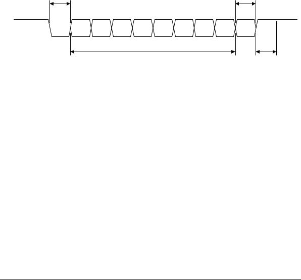
If the keyboard is not transmitting or if the system decides to override the keyboard output, the system forces the clock line LOW for more than 60μs while preparing to send. When the system is ready to send (data line will be LOW), it allows the clock to go to a HIGH level.
The keyboard checks the status of the clock line at intervals of no more than 8ms. If a request-to-send is detected, the keyboard counts eleven bits. After the tenth bit the keyboard forces the data line LOW, and counts one more bit (the stop bit). This is the line control which acknowledges to the system that the keyboard has received the data. Upon receipt of this signal the PrimeCell KMI returns a ready state, in which it can accept keyboard output.
If the keyboard data line is detected with a LOW level following the tenth bit (no stop bit), a framing error has occurred and the keyboard continues to count until the data line becomes HIGH. The keyboard then forces the data line LOW and sends a Resend.
Each system command or data transmission to the keyboard requires a response from the keyboard before the system can send its next output. The keyboard should respond within 16ms unless the system prevents the keyboard output. If the keyboard response is invalid or has a parity error, the system should send the command or data again.
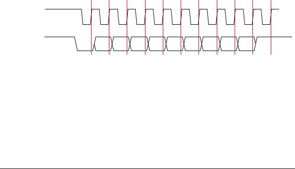
Figure 2-3 and Figure 2-4 illustrate data sent from the keyboard and data sent to the keyboard respectively.
1 |
2 |
3 |
4 |
5 |
6 |
7 |
8 |
9 |
10 |
11 |
KMICLK
KMIDATA |
0 |
1 |
2 |
3 |
4 |
5 |
6 |
7 Parity Stop |
Figure 2-3 Data sent from the keyboard (KMI receive)
2-10 |
© Copyright ARM Limited 1999. All rights reserved. |
DDI 0143C |