


Chapter 2
Functional Overview
This chapter provides an overview of the PrimeCell MultiMedia Card Interface (MMCI) and its interface with the multimedia card system. It contains the following sections:
•About the ARM PrimeCell MMCI (PL181) on page 2-2
•PrimeCell MMCI adapter on page 2-4
•APB interface on page 2-19
•Timing requirements on page 2-23.
ARM DDI 0205B |
Copyright © 2000, 2001 ARM Limited. All rights reserved. |
2-1 |

Functional Overview
2.1About the ARM PrimeCell MMCI (PL181)
The PrimeCell MMCI provides an interface between the APB system bus and multimedia cards. It consists of two parts:
•The PrimeCell MMCI adapter block provides all functions specific to the multimedia card. These include the clock generation unit, power management control, command and data transfer (see PrimeCell MMCI adapter on page 2-4 for more information).
•The APB interface provides access to the PrimeCell MMCI adapter registers, and generates interrupt and DMA request signals (see APB interface on page 2-19 for more information).
You can connect up to 30 cards as a multimedia card bus.
The PrimeCell MMCI uses two clock signals, each with a maximum frequency of 100 MHz. One or both clocks can be switched off for power saving:
•PrimeCell MMCI adapter clock (MCLK)
•APB bus clock (PCLK).
The relationship between MCLK and PCLK is defined below:
fp ≥ 3fm
--
8
where p = PCLK and m = MCLK.
2-2 |
Copyright © 2000, 2001 ARM Limited. All rights reserved. |
ARM DDI 0205B |
Functional Overview
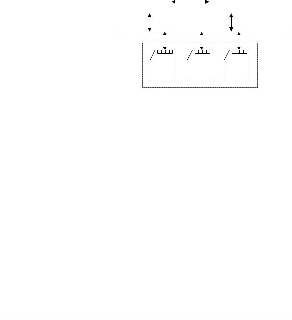
Figure 2-1 shows the multimedia card system.
Power |
|
|
|
MMCI |
supply |
|
|
|
|
|
|
|
|
|
|
|
|
|
|
Multimedia card bus
Card |
Card |
Card |
Multimedia card stack
Figure 2-1 Multimedia card system
The multimedia card system provides communication and data storage, and consists of:
•A multimedia card stack. This can consist of up to 30 cards on a single physical bus.
•A multimedia card controller: This is the multimedia card master, and provides an interface between a system bus and the multimedia card bus.
Multimedia cards are grouped into three types according to their function:
•Read Only Memory (ROM) cards, containing preprogrammed data
•Read/Write (R/W) cards, used for mass storage
•Input/Output (I/O) cards, used for communication.
The multimedia card system transfers commands and data using three signal lines:
CLK |
One bit is transferred on both command and data lines with each clock |
|
|
cycle. The clock frequency varies between 0MHz and 20MHz. |
|
CMD |
Bidirectional command channel that initializes a card and transfers |
|
|
commands. CMD has two operational modes: |
|
|
• |
Open-drain for initialization |
|
• |
Push-pull for command transfer. |
DAT |
Bidirectional data channel, operating in push-pull mode. |
|
ARM DDI 0205B |
Copyright © 2000, 2001 ARM Limited. All rights reserved. |
2-3 |