
6.Experiments
.pdf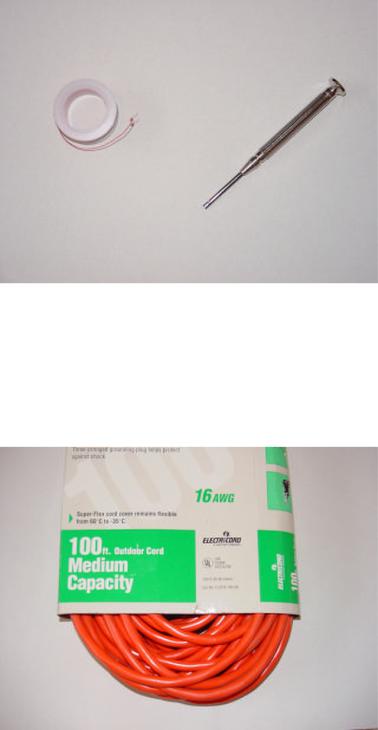
1.2. SETTING UP A HOME LAB |
13 |
======================================
Large wire (14 gauge and bigger) may be needed for building circuits that carry signi¯cant levels of current. Though electrical wire of practically any gauge may be purchased on spools, I have found a very inexpensive source of stranded (°exible), copper wire, available at any hardware store: cheap extension cords. Typically comprised of three wires colored white, black, and green, extension cords are often sold at prices less than the retail cost of the constituent wire alone. This is especially true if the cord is purchased on sale! Also, an extension cord provides you with a pair of 120 volt connectors: male (plug) and female (receptacle) that may be used for projects powered by 120 volts.
Extension cord, in package
14 |
CHAPTER 1. INTRODUCTION |
To extract the wires, carefully cut the outer layer of plastic insulation away using a utility knife. With practice, you may ¯nd you can peel away the outer insulation by making a short cut in it at one end of the cable, then grasping the wires with one hand and the insulation with the other and pulling them apart. This is, of course, much preferable to slicing the entire length of the insulation with a knife, both for safety's sake and for the sake of avoiding cuts in the individual wires' insulation.
======================================
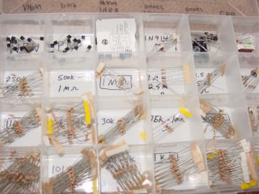
During the course of building many circuits, you will accumulate a large number of small components. One technique for keeping these components organized is to keep them in a plastic "organizer" box like the type used for ¯shing tackle.
Component box
In this view of one of my component boxes, you can see plenty of 1/8 watt resistors, transistors, diodes, and even a few 8-pin integrated circuits ("chips"). Labels for each compartment were made with a permanent ink marker.
1.3Contributors
Contributors to this chapter are listed in chronological order of their contributions, from most recent to ¯rst. See Appendix 2 (Contributor List) for dates and contact information.
Michael Warner (April 9, 2002): Suggestions for a section describing home laboratory setup.
Chapter 2
BASIC CONCEPTS AND TEST EQUIPMENT
2.1Voltmeter usage
PARTS AND MATERIALS
²Multimeter, digital or analog
²Assorted batteries
²One light-emitting diode (Radio Shack catalog # 276-026 or equivalent)
²Small "hobby" motor, permanent-magnet type (Radio Shack catalog # 273-223 or equivalent)
²Two jumper wires with "alligator clip" ends (Radio Shack catalog # 278-1156, 278-1157, or equivalent)
A multimeter is an electrical instrument capable of measuring voltage, current, and resistance. Digital multimeters have numerical displays, like digital clocks, for indicating the quantity of voltage, current, or resistance. Analog multimeters indicate these quantities by means of a moving pointer over a printed scale.
Analog multimeters tend to be less expensive than digital multimeters, and more bene¯cial as learning tools for the ¯rst-time student of electricity. I strongly recommend purchasing an analog multimeter before purchasing a digital multimeter, but to eventually have both in your tool kit for these experiments.
CROSS-REFERENCES
Lessons In Electric Circuits, Volume 1, chapter 1: "Basic Concepts of Electricity" Lessons In Electric Circuits, Volume 1, chapter 8: "DC Metering Circuits"
LEARNING OBJECTIVES
² How to measure voltage
15

16 |
CHAPTER 2. BASIC CONCEPTS AND TEST EQUIPMENT |
²Characteristics of voltage: existing between two points
²Selection of proper meter range
ILLUSTRATION
|
Digital |
|
|
multimeter |
|
V |
A |
|
|
Analog |
|
|
multimeter |
|
V |
A |
|
OFF |
|
|
A |
- |
+ |
COM |
|
|
Test leads |
|
Test leads |
Test probes |
Test probes |
2.1. VOLTMETER USAGE |
17 |
-
+
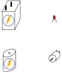
Light-emitting diode ("LED")
6-volt "lantern" battery
Permanentmagnet motor
1.5-volt "D-cell" battery
INSTRUCTIONS
In all the experiments in this book, you will be using some sort of test equipment to measure aspects of electricity you cannot directly see, feel, hear, taste, or smell. Electricity { at least in small, safe quantities { is insensible by our human bodies. Your most fundamental "eyes" in the world of electricity and electronics will be a device called a multimeter. Multimeters indicate the presence of, and measure the quantity of, electrical properties such as voltage, current, and resistance. In this experiment, you will familiarize yourself with the measurement of voltage.
Voltage is the measure of electrical "push" ready to motivate electrons to move through a conductor. In scienti¯c terms, it is the speci¯c energy per unit charge, mathematically de¯ned as joules per coulomb. It is analogous to pressure in a °uid system: the force that moves °uid through a pipe, and is measured in the unit of the Volt (V).
Your multimeter should come with some basic instructions. Read them well! If your multimeter is digital, it will require a small battery to operate. If it is analog, it does not need a battery to measure voltage.
Some digital multimeters are autoranging. An autoranging meter has only a few selector switch (dial) positions. Manual-ranging meters have several di®erent selector positions for each basic quantity: several for voltage, several for current, and several for resistance. Autoranging is usually found on only the more expensive digital meters, and is to manual ranging as an automatic transmission is to a manual transmission in a car. An autoranging meter "shifts gears" automatically to ¯nd the best measurement range to display the particular quantity being measured.
Set your multimeter's selector switch to the highest-value "DC volt" position available. Autoranging multimeters may only have a single position for DC voltage, in which case you need to set the switch to that one position. Touch the red test probe to the positive (+) side of a battery, and the black test probe to the negative (-) side of the same battery. The meter should now provide you with some sort of indication. Reverse the test probe connections to the battery if the meter's indication is negative (on an analog meter, a negative value is indicated by the pointer de°ecting left instead of right).
18 |
CHAPTER 2. BASIC CONCEPTS AND TEST EQUIPMENT |
If your meter is a manual-range type, and the selector switch has been set to a high-range position, the indication will be small. Move the selector switch to the next lower DC voltage range setting and reconnect to the battery. The indication should be stronger now, as indicated by a greater de°ection of the analog meter pointer (needle), or more active digits on the digital meter display. For the best results, move the selector switch to the lowest-range setting that does not "over-range" the meter. An over-ranged analog meter is said to be "pegged," as the needle will be forced all the way to the right-hand side of the scale, past the full-range scale value. An over-ranged digital meter sometimes displays the letters "OL", or a series of dashed lines. This indication is manufacturer-speci¯c.
What happens if you only touch one meter test probe to one end of a battery? How does the meter have to connect to the battery in order to provide an indication? What does this tell us about voltmeter use and the nature of voltage? Is there such a thing as voltage "at" a single point?
Be sure to measure more than one size of battery, and learn how to select the best voltage range on the multimeter to give you maximum indication without over-ranging.
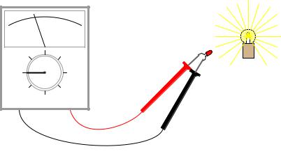
Now switch your multimeter to the lowest DC voltage range available, and touch the meter's test probes to the terminals (wire leads) of the light-emitting diode (LED). An LED is designed to produce light when powered by a small amount of electricity, but LEDs also happen to generate DC voltage when exposed to light, somewhat like a solar cell. Point the LED toward a bright source of light with your multimeter connected to it, and note the meter's indication:
Light source
LED |
- 
 +
+
Batteries develop electrical voltage through chemical reactions. When a battery "dies," it has exhausted its original store of chemical "fuel." The LED, however, does not rely on an internal "fuel" to generate voltage; rather, it converts optical energy into electrical energy. So long as there is light to illuminate the LED, it will produce voltage.
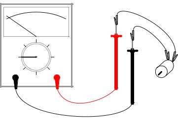
Another source of voltage through energy conversion a generator. The small electric motor speci¯ed in the "Parts and Materials" list functions as an electrical generator if its shaft is turned by a mechanical force. Connect your voltmeter (your multimeter, set to the "volt" function) to the motor's terminals just as you connected it to the LED's terminals, and spin the shaft with your ¯ngers. The meter should indicate voltage by means of needle de°ection (analog) or numerical readout (digital).
If you ¯nd it di±cult to maintain both meter test probes in connection with the motor's terminals while simultaneously spinning the shaft with your ¯ngers, you may use alligator clip "jumper" wires
2.1. VOLTMETER USAGE |
19 |
like this:
Jumper
wire
Alligator clip
- |
+ |
|
Motor |
Determine the relationship between voltage and generator shaft speed? Reverse the generator's direction of rotation and note the change in meter indication. When you reverse shaft rotation, you change the polarity of the voltage created by the generator. The voltmeter indicates polarity by direction of needle direction (analog) or sign of numerical indication (digital). When the red test lead is positive (+) and the black test lead negative (-), the meter will register voltage in the normal direction. If the applied voltage is of the reverse polarity (negative on red and positive on black), the meter will indicate "backwards."
20 |
CHAPTER 2. BASIC CONCEPTS AND TEST EQUIPMENT |
2.2Ohmmeter usage
PARTS AND MATERIALS
²Multimeter, digital or analog
²Assorted resistors (Radio Shack catalog # 271-312 is a 500-piece assortment)
²Rectifying diode (1N4001 or equivalent; Radio Shack catalog # 276-1101)
²Cadmium Sulphide photocell (Radio Shack catalog # 276-1657)
²Breadboard (Radio Shack catalog # 276-174 or equivalent)
²Jumper wires
²Paper
²Pencil
²Glass of water
²Table salt
This experiment describes how to measure the electrical resistance of several objects. You need not possess all items listed above in order to e®ectively learn about resistance. Conversely, you need not limit your experiments to these items. However, be sure to never measure the resistance of any electrically "live" object or circuit. In other words, do not attempt to measure the resistance of a battery or any other source of substantial voltage using a multimeter set to the resistance ("ohms") function. Failing to heed this warning will likely result in meter damage and even personal injury.
CROSS-REFERENCES
Lessons In Electric Circuits, Volume 1, chapter 1: "Basic Concepts of Electricity" Lessons In Electric Circuits, Volume 1, chapter 8: "DC Metering Circuits"
LEARNING OBJECTIVES
²Determination and comprehension of "electrical continuity"
²Determination and comprehension of "electrically common points"
²How to measure resistance
²Characteristics of resistance: existing between two points
²Selection of proper meter range
²Relative conductivity of various components and materials
2.2. OHMMETER USAGE |
21 |
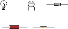
ILLUSTRATION
Diode
Incandescent Photocell
lamp
Resistor Resistor
INSTRUCTIONS
Resistance is the measure of electrical "friction" as electrons move through a conductor. It is measured in the unit of the "Ohm," that unit symbolized by the capital Greek letter omega (-).
Set your multimeter to the highest resistance range available. The resistance function is usually denoted by the unit symbol for resistance: the Greek letter omega (-), or sometimes by the word "ohms." Touch the two test probes of your meter together. When you do, the meter should register 0 ohms of resistance. If you are using an analog meter, you will notice the needle de°ect full-scale when the probes are touched together, and return to its resting position when the probes are pulled apart. The resistance scale on an analog multimeter is reverse-printed from the other scales: zero resistance in indicated at the far right-hand side of the scale, and in¯nite resistance is indicated at the far left-hand side. There should also be a small adjustment knob or "wheel" on the analog multimeter to calibrate it for "zero" ohms of resistance. Touch the test probes together and move this adjustment until the needle exactly points to zero at the right-hand end of the scale.
Although your multimeter is capable of providing quantitative values of measured resistance, it is also useful for qualitative tests of continuity: whether or not there is a continuous electrical connection from one point to another. You can, for instance, test the continuity of a piece of wire by connecting the meter probes to opposite ends of the wire and checking to see the the needle moves full-scale. What would we say about a piece of wire if the ohmmeter needle didn't move at all when the probes were connected to opposite ends?
Digital multimeters set to the "resistance" mode indicate non-continuity by displaying some non-numerical indication on the display. Some models say "OL" (Open-Loop), while others display dashed lines.
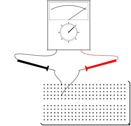
Use your meter to determine continuity between the holes on a breadboard: a device used for temporary construction of circuits, where component terminals are inserted into holes on a plastic grid, metal spring clips underneath each hole connecting certain holes to others. Use small pieces of 22-gauge solid copper wire, inserted into the holes of the breadboard, to connect the meter to these spring clips so that you can test for continuity:
22 |
CHAPTER 2. BASIC CONCEPTS AND TEST EQUIPMENT |
Continuity!
Analog
meter
- 
 +
+
22-gauge wire |
22-gauge wire |
|
|
|
|
|
|
|
|
|
|
|
|
|
Breadboard
