

6.Experiments
.pdf3.9. RHEOSTAT RANGE LIMITING |
103 |
||
|
|
|
|
|
|
|
|
|
|
|
|
 V
V  A
A
V A
OFF
A COM
Suppose we wanted to elevate the lower end of this resistance range so that we had an adjustable range from 10 k- to 20 k- with a full sweep of the potentiometer's adjustment. This could be easily accomplished by adding a 10 k- resistor in series with the potentiometer. Add one to the circuit as shown and re-measure total resistance while adjusting the potentiometer:

104 |
|
CHAPTER 3. DC CIRCUITS |
|
|
|
|
|
|
|
|
|
 V
V  A
A
V A
OFF
A COM
A shift in the low end of an adjustment range is called a zero calibration, in metrological terms. With the addition of a series 10 k- resistor, the "zero point" was shifted upward by 10,000 -. The di®erence between high and low ends of a range { called the span of the circuit { has not changed, though: a range of 10 k- to 20 k- has the same 10,000 - span as a range of 0 - to 10 k-. If we wish to shift the span of this rheostat circuit as well, we must change the range of the potentiometer itself. We could replace the potentiometer with one of another value, or we could simulate a lowervalue potentiometer by placing a resistor in parallel with it, diminishing its maximum obtainable resistance. This will decrease the span of the circuit from 10 k- to something less.
Add a 10 k- resistor in parallel with the potentiometer, to reduce the span to one-half of its former value: from 10 K- to 5 k-. Now the calibrated resistance range of this circuit will be 10 k- to 15 k-:

3.9. RHEOSTAT RANGE LIMITING |
105 |
||
|
|
|
|
|
|
|
|
|
|
|
|
 V
V  A
A
V A
OFF
A COM
There is nothing we can do to increase the span of this rheostat circuit, short of replacing the potentiometer with another of greater total resistance. Adding resistors in parallel can only decrease the span. However, there is no such restriction with calibrating the zero point of this circuit, as it began at 0 - and may be made as great as we wish by adding resistance in series.
A multitude of resistance ranges may be obtained using only 10 K- ¯xed-value resistors, if we are creative with series-parallel combinations of them. For instance, we can create a range of 7.5 k- to 10 k- by building the following circuit:

106 |
CHAPTER 3. DC CIRCUITS |
Rtotal
0 to 2.5 kΩ
|
2.5 kΩ |
5 kΩ |
|
|
|
|
|
|
|
|||||||
|
|
|
|
|
|
|
|
|||||||||
|
|
|
|
|
|
|
|
|||||||||
|
|
|
|
|
|
|
|
|
|
|
|
|
|
|
|
|
|
|
|
|
|
|
|
|
|
|
|
|
|
|
|
|
|
|
|
|
|
|
|
|
|
|
|
|
|
|
|
|
|
|
|
|
|
|
|
|
|
|
|
|
|
|
|
|
|
|
|
|
|
|
|
|
|
|
|
|
|
|
|
|
|
|
|
|
|
|
|
|
|
|
|
|
|
|
|
|
|
|
|
|
|
|
|
|
|
|
|
|
|
|
|
|
|
|
|
|
|
|
All resistors = 10 kΩ
 V
V  A
A
V A
OFF
A COM
Creating a custom resistance range from ¯xed-value resistors and a potentiometer is a very useful technique for producing precise resistances required for certain circuits, especially meter circuits. In many electrical instruments { multimeters especially { resistance is the determining factor for the instrument's range of measurement. If an instrument's internal resistance values are not precise, neither will its indications be. Finding a ¯xed-value resistor of just the right resistance for placement
3.9. RHEOSTAT RANGE LIMITING |
107 |
in an instrument circuit design is unlikely, so custom resistance "networks" may need to be built to provide the desired resistance. Having a potentiometer as part of the resistor network provides a means of correction if the network's resistance should "drift" from its original value. Designing the network for minimum span ensures that the potentiometer's e®ect will be small, so that precise adjustment is possible and so that accidental movement of its mechanism will not result in severe calibration errors.
Experiment with di®erent resistor "networks" and note the e®ects on total resistance range.

108 |
CHAPTER 3. DC CIRCUITS |
3.10Thermoelectricity
PARTS AND MATERIALS
²Length of bare (uninsulated) copper wire
²Length of bare (uninsulated) iron wire
²Candle
²Ice cubes
Iron wire may be obtained from a hardware store. If some cannot be found, aluminum wire also works.
CROSS-REFERENCES
Lessons In Electric Circuits, Volume 1, chapter 9: "Electrical Instrumentation Signals"
LEARNING OBJECTIVES
²Thermocouple function and purpose
²Seebeck e®ect without a junction between two dissimilar metals
SCHEMATIC DIAGRAM
Thermocouple |
+ |
|
V Voltmeter |
||
|
||
|
- |
|
ILLUSTRATION |
|

3.10. THERMOELECTRICITY |
109 |
|
|
|
|
|
|
|
|
|
|


 V
V 


 A
A


 V
V 


 A
A
OFF
A COM
iron wire copper wire
Candle
INSTRUCTIONS
Twist one end of the iron wire together with one end of the copper wire. Connect the free ends of these wires to respective terminals on a terminal strip. Set your voltmeter to its most sensitive range and connect it to the terminals where the wires attach. The meter should indicate nearly zero voltage.
What you have just constructed is a thermocouple: a device which generates a small voltage proportional to the temperature di®erence between the tip and the meter connection points. When the tip is at a temperature equal to the terminal strip, there will be no voltage produced, and thus no indication seen on the voltmeter.
Light a candle and insert the twisted-wire tip into the °ame. You should notice an indication on your voltmeter. Remove the thermocouple tip from the °ame and let cool until the voltmeter indication is nearly zero again. Now, touch the thermocouple tip to an ice cube and note the voltage indicated by the meter. Is it a greater or lesser magnitude than the indication obtained with the °ame? How does the polarity of this voltage compare with that generated by the °ame?
After touching the thermocouple tip to the ice cube, warm it by holding it between your ¯ngers. It may take a short while to reach body temperature, so be patient while observing the voltmeter's indication.
A thermocouple is an application of the Seebeck e®ect: the production of a small voltage proportional to a temperature gradient along the length of a wire. This e®ect is not well understood,
110 |
CHAPTER 3. DC CIRCUITS |
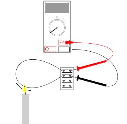
even by those familiar with thermocouples, and it is not speci¯c to a junction of two di®erent ("dissimilar") metals. The Seebeck e®ect may be observed along a length of continuous wire, like this:


 V
V 


 A
A


 V
V 


 A
A
OFF
A COM
iron wire
Candle (moving)
Form a loop of bare wire from one terminal of the terminal strip to the other. Apply heat to a location on the wire, using the lit candle, and slowly move the candle °ame along the wire's length. Note the voltmeter indication, and how it corresponds to candle °ame speed and direction.
Remove the candle °ame from the wire and allow time for the wire to cool. Replace the bare wire with another loop of bare wire of a di®erent metal (copper instead of iron, or visa-versa). Repeat the experiment of subjecting the wire to a moving source of heat. Di®erent metals generate di®erent amounts of "Seebeck voltage" for the same temperature gradients. Try to determine which metal(s) generate the most voltage for the same heating conditions.
Thermocouples, being made of two dissimilar metals joined at one end, produce voltage without the need of a moving heat source because the same static temperature gradient along both wires (from tip to terminal strip) produces di®erent Seebeck voltages along those wires' lengths. The resultant voltage between the two free wire ends is the di®erence between the two Seebeck voltages.

3.10. THERMOELECTRICITY |
111 |
||
|
iron wire voltage |
|
|
HOT |
COOL |
Resultant |
|
voltage |
|||
|
|
||
|
copper wire voltage |
|
|
Thermocouples are widely used as temperature-sensing devices because the mathematical relationship between temperature di®erence and resultant voltage is both repeatable and fairly linear. By measuring voltage, it is possible to infer temperature. Di®erent ranges of temperature measurement are possible by selecting di®erent metal pairs to be joined together.
112 |
CHAPTER 3. DC CIRCUITS |
3.11Make your own multimeter
PARTS AND MATERIALS
²Sensitive meter movement (Radio Shack catalog # 22-410)
²Selector switch, single-pole, multi-throw, break-before-make (Radio Shack catalog # 275-1386 is a 2-pole, 6-position unit that works well)
²Multi-turn potentiometers, PCB mount (Radio Shack catalog # 271-342 and 271-343 are 15turn, 1 k- and 10 k- "trimmer" units, respectively)
²Assorted resistors, preferably high-precision metal ¯lm or wire-wound types (Radio Shack catalog # 271-309 is an assortment of metal-¯lm resistors, +/- 1% tolerance)
²Plastic or metal mounting box
²Three "banana" jack style binding posts, or other terminal hardware, for connection to potentiometer circuit (Radio Shack catalog # 274-662 or equivalent)
The most important and expensive component in a meter is the movement: the actual needle- and-scale mechanism whose task it is to translate an electrical current into mechanical displacement where it may be visually interpreted. The ideal meter movement is physically large (for ease of viewing) and as sensitive as possible (requires minimal current to produce full-scale de°ection of the needle). High-quality meter movements are expensive, but Radio Shack carries some of acceptable quality that are reasonably priced. The model recommended in the parts list is sold as a voltmeter with a 0-15 volt range, but is actually a milliammeter with a range ("multiplier") resistor included separately.
It may be cheaper to purchase an inexpensive analog meter and disassemble it for the meter movement alone. Although the thought of destroying a working multimeter in order to have parts to make your own may sound counter-productive, the goal here is learning, not meter function.
I cannot specify resistor values for this experiment, as these depend on the particular meter movement and measurement ranges chosen. Be sure to use high-precision ¯xed-value resistors rather than carbon-composition resistors. Even if you happen to ¯nd carbon-composition resistors of just the right value(s), those values will change or "drift" over time due to aging and temperature °uctuations. Of course, if you don't care about the long-term stability of this meter but are building it just for the learning experience, resistor precision matters little.
CROSS-REFERENCES
Lessons In Electric Circuits, Volume 1, chapter 8: "DC Metering Circuits"
LEARNING OBJECTIVES
²Voltmeter design and use
²Ammeter design and use
²Rheostat range limiting
²Calibration theory and practice