

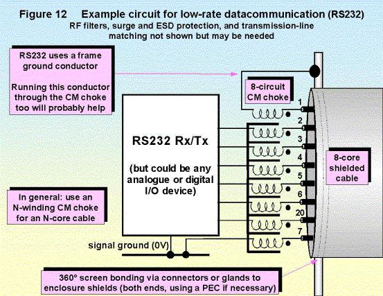
Where a conductor has N cores, it is best to connect it to the electronics at each end with a CM choke with N windings. Figure 12 shows a seven winding choke used for an eight-core cable, because one of the conductors is dedicated to “frame ground” according to the RS232 standard. (The frame ground lead is not likely to carry heavy currents and require a PEC because RS232 is only used for short-distances.)
RS232 only suits short distances because its single-ended signals lose their integrity rapidly as they radiate their energy as emissions. So although figure 12 (and the bottom circuit in figure 11) looks easy enough, the use of single-ended signals will require attention to CM choke and/or cable and/or connector quality. (Cable and connector types and qualities are discussed in the 2nd part of this series.)
Using drivers with very slow output edges (preferably slew-rate limited) can ease emissions problems significantly. Alternatively, standard drivers can be passively filtered to reduce their high-frequency content.
1.4.3Opto-isolation
Opto-isolation is a common technique for digital signals, but the input-output capacitance of typical opto-coupler is around 1 pF – this creates a low enough impedance at frequencies above 10MHz to interact with the circuit impedances and destroy the balance of the signals in the cable.
As before, the selection of a suitable common-mode choke will restore the balance at high frequencies, allowing fast-edged signals to be communicated with fewer emissions or immunity problems.
Figure 13 shows an example of good EMC practices in a high-speed optically isolated link.
Design techniques for EMC – Part1 |
Cherry Clough Consultants July 2001 |
Page 22 of 26 |
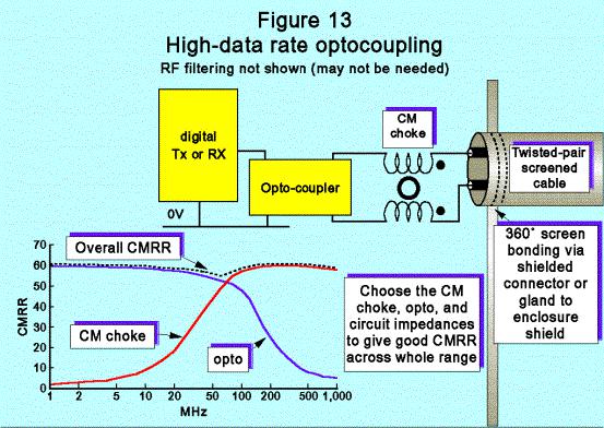
Similar to the previous examples, the CMRR of the CM choke is chosen to compensate for the fall-off in the balance of the opto-isolator at high frequencies, so that a good balance (equal to a good CMRR) is maintained across the full frequency range (DC to 1GHz in this example).
In many cases the CM choke can be replaced by two individual ferrite beads, and sometimes no choke or ferrites at all prove to be necessary.
But if they are not placed and routed on the PCB Murphy’s Law predicts that they will be needed, and furthermore it is likely that there will be no room for them, no doubt making a wholesale redesign of the product necessary, including its plastic enclosure.
If the cable needs to be shielded, it must be 360° bonding via a shielded connector or gland to enclosure shield at both ends, using a PEC if necessary (see IEC 61000-5-2). But where galvanic isolation is needed bonding the shield at both ends may be forbidden. In this case a capacitive bond at one end may be used (the capacitor rated for the full voltage, and probably safety-approved too) - or the shield left unterminated at one end, which is liable to have poor EMC performance.
Analogue signals can now benefit also from opto-isolation with up to 0.1% linearity (e.g. using IL300 and the like). This can save having to use voltage-frequency converters (and vice-versa) in many opto-coupled applications.
Because of the common drawing practice of not showing power rails in full, it sometimes happens that both sides of an opto-isolator are powered form the same DC power rails, seriously compromising the isolation achieved and the RF performance. The RF performance of opto-isolators can only be as good as the RF isolation between their power supplies.
1.4.4External I/O protection
External I/O is exposed to the full range of electromagnetic phenomena. The better circuits in the above figures should need less filtering or protection, for a given signal and semiconductors.
All the above communication circuits may need additional filtering for emissions or immunity with continuous EMC phenomena.
For ESD, transient, and surge phenomena the upper circuits of figures 9 and 11, and figure 13, are well-protected – providing their isolating transformers or opto-couplers will withstand the voltage stresses applied. RF filtering can also give some protection against ESD or fast transients.
Design techniques for EMC – Part1 |
Cherry Clough Consultants July 2001 |
Page 23 of 26 |
The above circuits without isolating transformers or opto-couplers will almost certainly need overvoltage protection with diodes or transient suppressors, although heavy filtering might be adequate if data rates or frequencies are very low. For control signals a series 10k or 100k resistor closest to the connector followed by a 100 nF or 10 nF capacitor to the PCB ground plane makes a marvellous barrier against almost all EMC phenomena, but does not allow rapid changes in logic state.
Digital communications generally need a robust digital protocol (see below) to prevent data corruption, as protection devices only prevent actual damage to the semiconductors.
Allow for additional protection devices on a prototype board, and test it as early as possible to see which are needed.
1.4.5“Earth – free” and “floating” communications
Another name for galvanic isolation is “earth free” or “floating”, but these terms are often misunderstood or misused.
The above circuits using isolating transformers or opto-couplers are all “earth-free” and “floating”, because no currents from the communications devices are assumed to flow between Tx and Rx via the 0V or chassis. This is true even though their cable screens are bonded at both ends to local chassis (enclosure shield). In fact, leakage currents flow through parasitic capacitances, and when CMRR is poor they can reach surprisingly large values.
The terms “earth-free” and “floating” are also sometimes applied to electronically balanced inputs or outputs, such as the lower circuit of figure 9. Although good CMRR performance will still give low leakage via 0V or chassis, such circuits are not galvanically isolated and are intrinsically more vulnerable to surges. Electronically balanced circuits also have a reputation for suffering from instability when one of the two lines is accidentally connected to ground.
Don't forget that the quality of the isolation achieved in practice is limited by the isolation performance of the power supplies supplying each side.
Never try to achieve “earth-free” operation by removing the protective earth from any equipment – this creates serious safety hazards and immediately contravenes several mandatory laws. If “ground loops” are a problem, use the proper circuit and installation techniques (e.g. PECs) and never compromise safety.
It is best to avoid jargon phrases like “earth-free” and “floating”, instead state what is actually required or meant in plain circuit terms.
When screens cannot be connected at both ends
In some applications it is mandatory not to connect equipment grounds via cable screens or other conductors. The equipment concerned is still connected to main supply system’s earth, but the earthing system is controlled in a special way. This does not help to achieve EMC at low cost. A screen connection at only one end will make the balance of the circuit and its conductors more important, and it will be more difficult and expensive to achieve a given EMC performance for a given signal.
Attention to creepage and clearances will also be important for safety reasons. In larger installations: when screens are not bonded at both ends, surges can cause arcing at the unconnected end possibly causing fire or toxic fumes. People can also receive shocks if they happen to be touching the screen and other equipment when a surge arrives. Clearly, not connecting the screens at both ends must place extra electrical and EMC stresses on some of the circuit components and cables, making surge, transient, and ESD damage more likely.
1.4.6Hazardous area and intrinsically safe communications
Special barrier devices to limit the maximum power available in normal and fault conditions, and other restrictions, may be required. The EMC performance of these devices, which are made by specialist companies, is crucial. Further discussion is beyond the scope of this series.
Design techniques for EMC – Part1 |
Cherry Clough Consultants July 2001 |
Page 24 of 26 |