

service-manual-samsung-r510
.pdf--
-This Document can not be used without Samsung's authorization -
3. Disassembly and Reassembly
3-1. Disassembly and Reassembly R510
|
|
|
|
|
[Caution] Attention to red sentence. |
|
|
|
|
|
|
Part |
|
|
Picture |
|
Description |
|
|
|
|
|
|
|
2 |
|
|
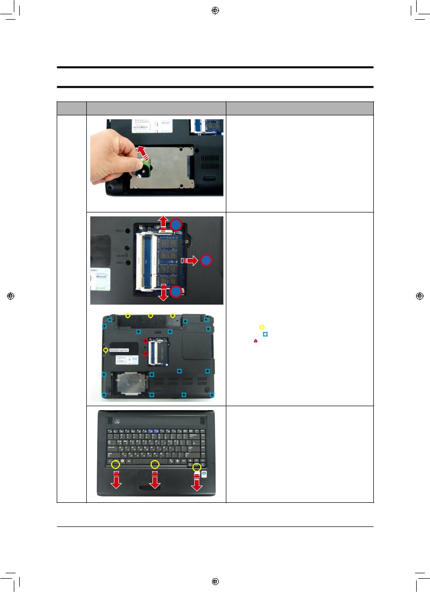
1. |
Before disassembling, the AC adaptor and Battery |
|
|
|
2 |
must be separated. |
|
|
|
|
|
2. |
AS mark No.1/2 put KNOB-Battery to end of each |
|
|
|
|
|
side, then pull the battery upward like outward |
|
1 |
1 |
|
||
3. After removing the Battery
Main
System 4. ODD and DOOR-HDD, DOOR-Memory Screw
Remove.
M2 X L4, Black (4EA)
- Yellow ( ): ODD Screw
- Skyblue ( ): HDD Door Screw
- Red ( ): Minicard Door Screw
5. HDD DOOR Remove,
MEMORY DOOR Remove
ODD Remove
3-1
3_Disassembly and Reassembly_eng1 1 |
|
|
|
|
|
|
|
||
|
|
|
|
|
|
|
|
|
|
--
-This Document can not be used without Samsung's authorization -
3. Disassembly and Reassembly
Part |
Picture |
Description |
6. Separate HDD by pulling in the arrow direction.
* Cautions
Avoid lifting HDD excessively, because Connector can be damaged.
7. ODD Remove
1
|
1 |
|
2 |
|
|
|
||||||
|
|
|
||||||||||
|
|
|
||||||||||
|
|
|
|
|
|
|
|
|||||
Main |
|
|
|
|
|
|
|
|
|
|
|
|
System |
|
|
|
|
|
|
|
|
|
|
8. Bottom Screw Remove |
|
|
|
|
|
|
|
|
|
|
|
|
- Yellow( |
): M2 X L4, Black (4EA) |
|
|
|
|
|
|
|
|
|
|
|
- Skyblue( |
): M2.6 X L8, Black (17EA) |
|
|
|
|
|
|
|
|
|
|
|
- Red( ): M2 X L6, (2EA) |
|
9. Push two keyboard hooks fixing a keyboard in the arrow direction
* Caution
When using a tool, be careful not to scratch the surface of Top and not to be hurt
3-2
3_Disassembly and Reassembly_eng2 2 |
|
|
|
|
|
|
|
||
|
|
|
|
|
|
|
|
|
|

--
-This Document can not be used without Samsung's authorization -
3. Disassembly and Reassembly
Part |
Picture |
Description |
10. When seperating the keyboard hook, use a tweeze, wood cutter or “-”screwdriver.
* Caution
Keyboard is connected to FPC, thus lift a little bit until FPC appear.
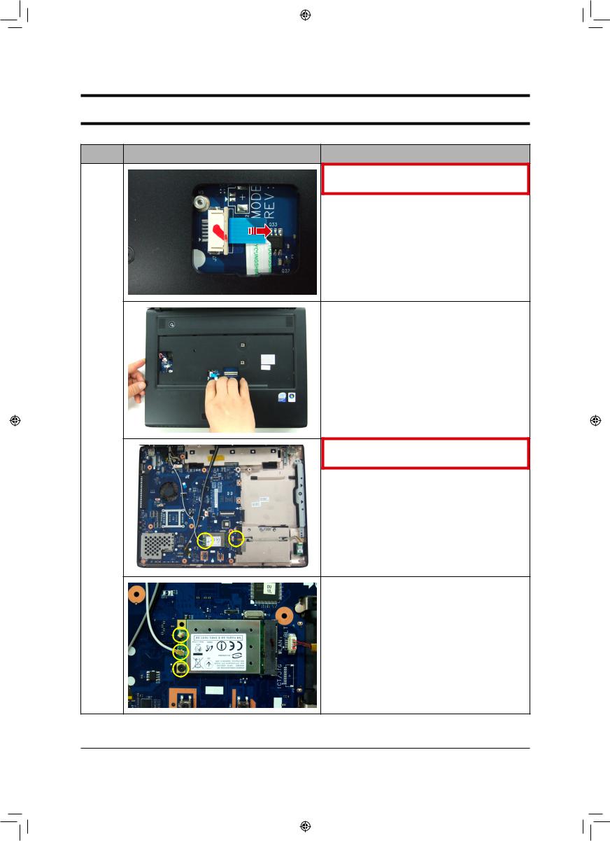
11. Lift up the cover of connector connected FPC of keyboard, and then pull out FPC, separate the keyboard.
* Caution
Avoid pulling the keyboard excessively at this time as the keyboard connector can become detached.
Main
System 12. Separate 3 CABLE from TOP ASSY (TOUCH_PAD / SPEAKER / MIC Cable)
13. Separate two cables for disassembling Top. (Audio / MIC.)
3-3
3_Disassembly and Reassembly_eng3 3 |
|
|
|
|
|
|
|
||
|
|
|
|
|
|
|
|
|
|
--
-This Document can not be used without Samsung's authorization -
3. Disassembly and Reassembly
Part |
Picture |
Description |
14. FPC Connector TouchPad FPC .
15. And Then Remove TOP ASSY by lift up
Main
System 16. Wireless LAN Card Bluetooth Main Board
.
17. Remove cables connected to Wireless LAN Card, remove screw and LAN Card.
3-4
C(MWEWWIQFP] ERH 6IEWWIQFP]CIRK |
|
--
-This Document can not be used without Samsung's authorization -
3. Disassembly and Reassembly
Part |
Picture |
Description |
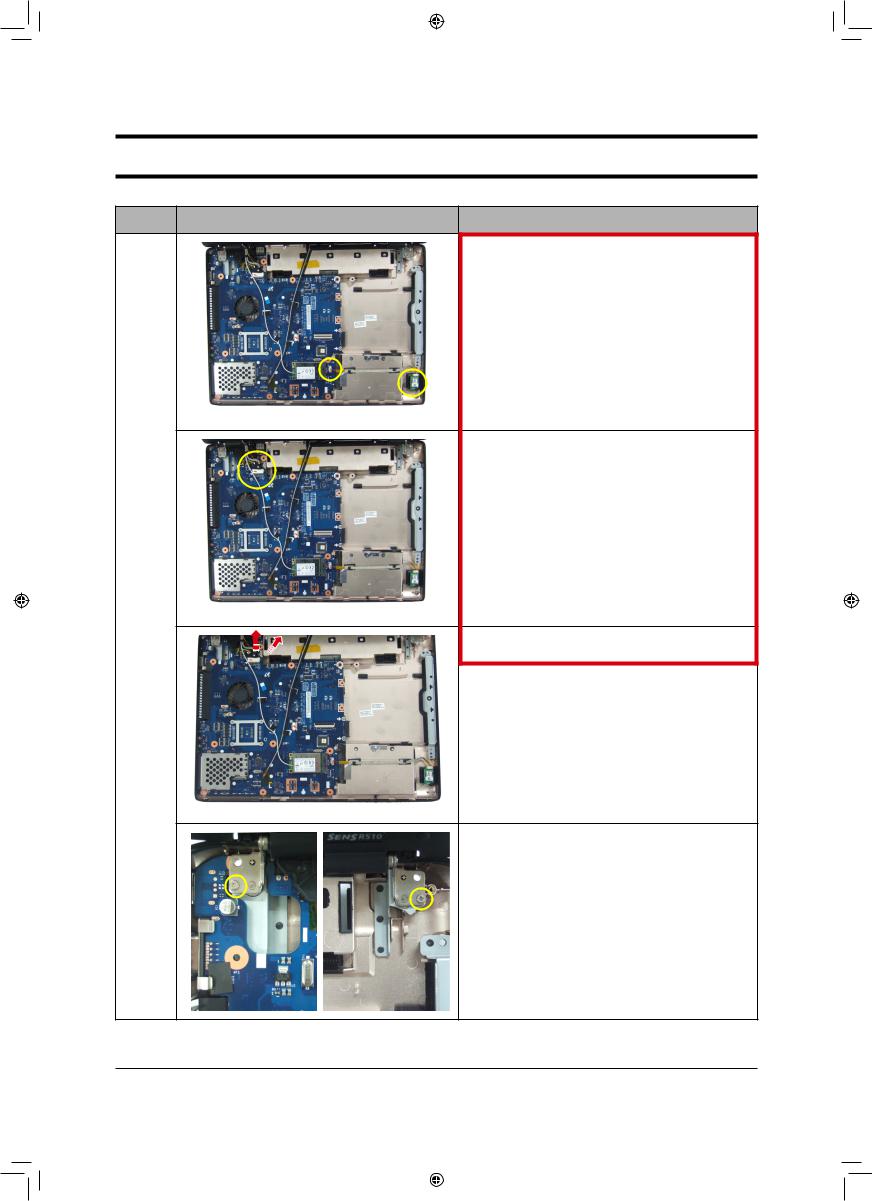
18. Bluetooth ConnectorBluetooth Cable , Screw Bluetooth Module .
M2 X L4, Black (1EA)
19. LCD Ass’y Main System2 Cable .
Main
System  20. Camera Cable LCD Cable
.
21. To separate LCD ASSY Remove 1 ,2 Screw
3-5
3_Disassembly and Reassembly_eng5 5 |
|
|
|
|
|
|
|
||
|
|
|
|
|
|
|
|
|
|
--
-This Document can not be used without Samsung's authorization -
3. Disassembly and Reassembly
Part |
Picture |
Description |
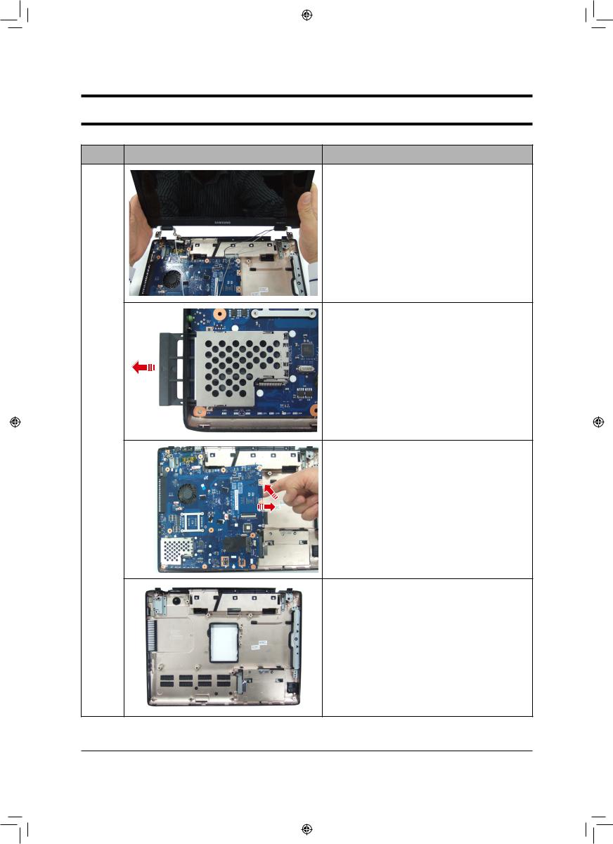
22. ASSY LCD and Bottom sys.
23. Remove Dummy Card in the direction of arrow.
Main |
|
System |
24. Lift up Main board following direction. |
|
25. BOTTOM
3-6
C(MWEWWIQFP] ERH 6IEWWIQFP]CIRK |
|
--
-This Document can not be used without Samsung's authorization -
3. Disassembly and Reassembly
Part |
Picture |
Description |
|
|
|
|
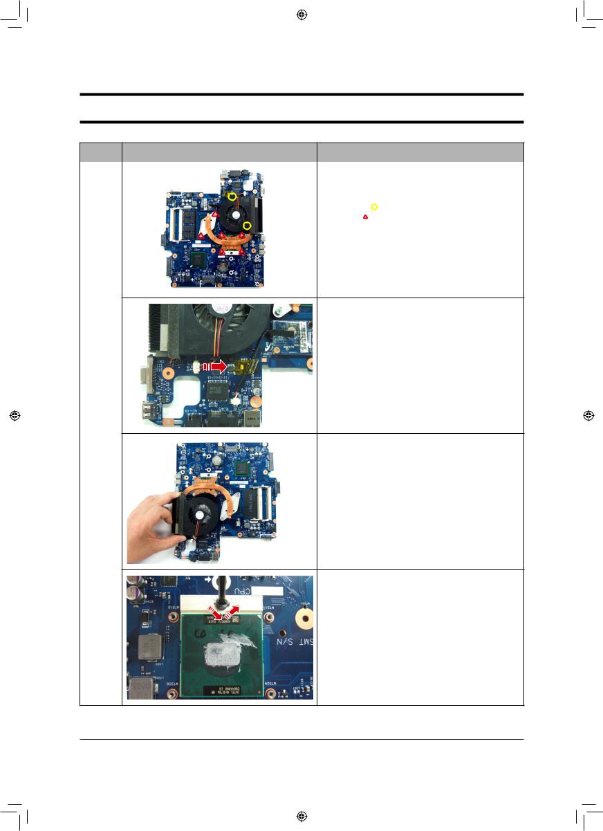
26. Remove |
screws for separating FAN and Heat |
|
sink. |
|
|
- Yellow ( |
): Screw (6EA) |
|
- Red ( ): M2 X L4, Black (2EA) |
|
27. Remove FAN CONNECTOR
Main
System
28. separating FAN and Heat sink.
29. Turn the screwdriver in the direction of anticlockwise and open CPU socket.
3-7
C(MWEWWIQFP] ERH 6IEWWIQFP]CIRK |
|
--
-This Document can not be used without Samsung's authorization -
3. Disassembly and Reassembly
Part |
Picture |
Description |
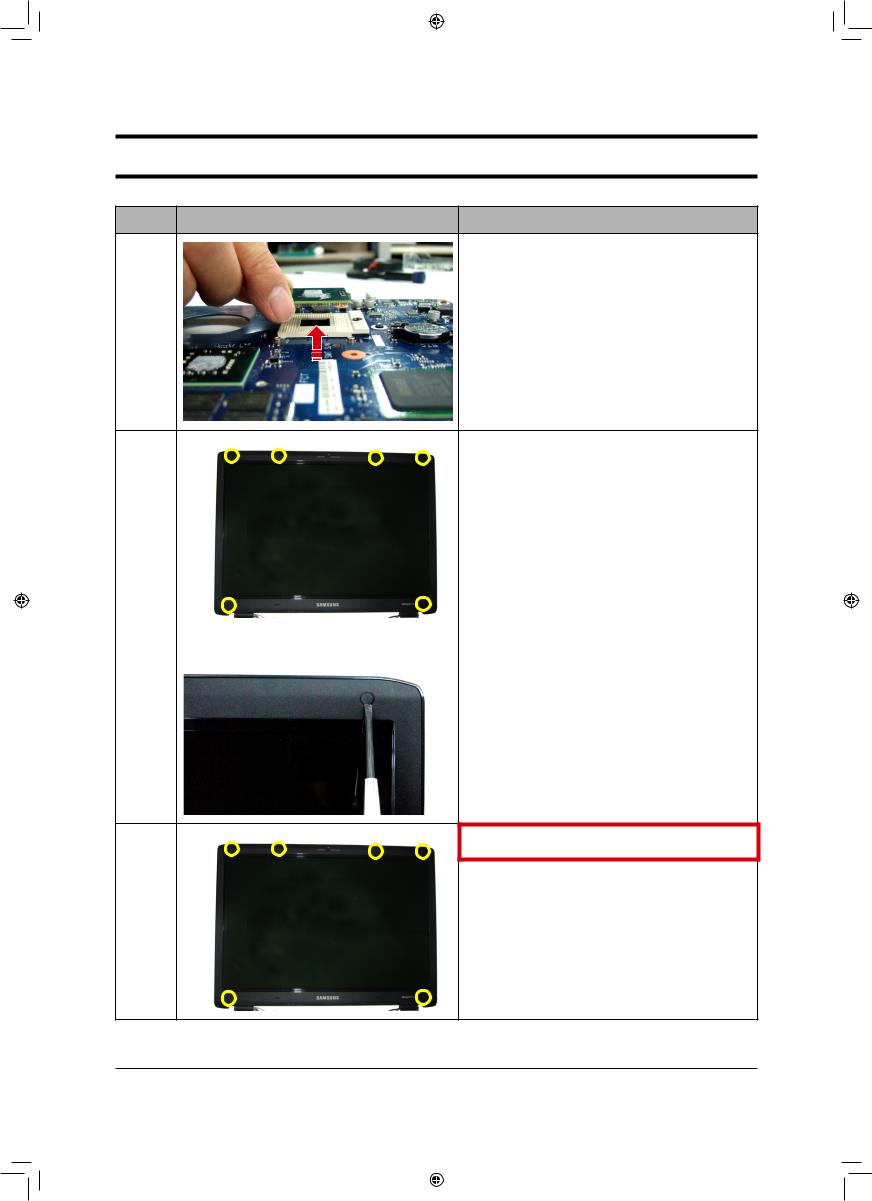
30. Hold up CPU.
31. Remove rubber-LCD-Cap & Screw on the LCD front.
* Caution
When using a tool, be careful not to scratch the surface of Top and not to be hurt.
32. 6 Screw . M2 X L6 (6EA)
3-8
3_Disassembly and Reassembly_eng8 8 |
|
|
|
|
|
|
|
||
|
|
|
|
|
|
|
|
|
|
--
-This Document can not be used without Samsung's authorization -
3. Disassembly and Reassembly
Part |
Picture |
Description |
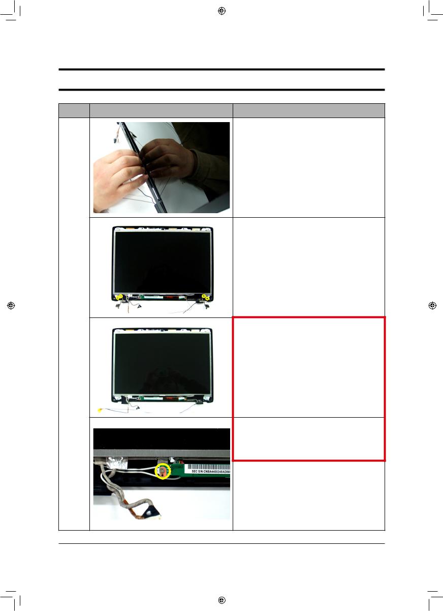
33. Separate LCD Front by twisting inside to outside like picture.
* Caution
When removing LCD Front, avoid twisting too strongly. If not, it can be bant.
34. Remove 4 screw in the Hinge
LCD
35. Hinge L, R
Ass'y
36. LCD Panel Ass’y INVERTER BD
Screw . M2 X L5 (1EA)
3-9
3_Disassembly and Reassembly_eng9 9 |
|
|
|
|
|
|
|
||
|
|
|
|
|
|
|
|
|
|
--
-This Document can not be used without Samsung's authorization -
3. Disassembly and Reassembly
Part |
Picture |
Description |
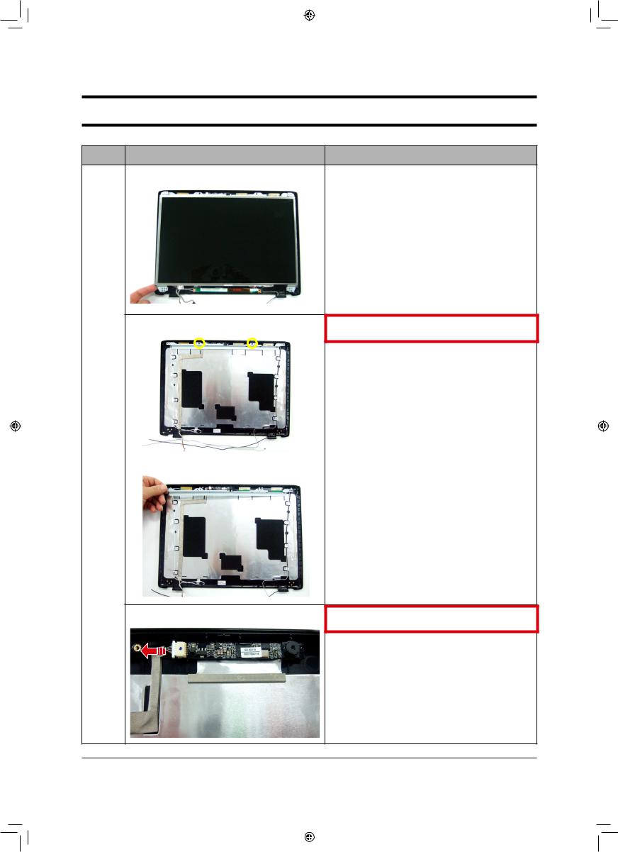
37. Separate Hinge and LCD-Panel like picture
38. Screw 2 , Bracket .
LCD
Ass'y
39. CAMERA MODULE CABLE
.
3-10
3_Disassembly and Reassembly_eng10 10 |
|
|
|
|
|
|
|
||
|
|
|
|
|
|
|
|
|
|