

CISSP - Certified Information Systems Security Professional Study Guide, 2nd Edition (2004)
.pdfOSI Model |
61 |
Part of the processing performed on the data within the Data Link layer includes adding the hardware source and destination addresses to the frame. The hardware address is the Media Access Control (MAC) address, which is a 6-byte address written in hexadecimal notation. The first 3 bytes of the address indicate the vendor or manufacturer of the physical network interface. The last 3 bytes represent a unique number assigned to that interface by the manufacturer. No two devices can have the same MAC address.
The Data Link layer contains two sublayers: the Logical Link Control (LLC) sublayer and the MAC sublayer. Details about these sublayers are not critical for the CISSP exam.
Network hardware devices that function at layer 2, the Data Link layer, are switches and bridges. These devices support MAC-based traffic routing. Switches receive a frame on one port and send it out another port based on the destination MAC address. MAC address destinations are used to determine whether a frame is transferred over the bridge from one network to another.
Network Layer
The Network layer (layer 3) is responsible for adding routing and addressing information to the data. The Network layer accepts the segment from the Transport layer and adds information to it to create a packet. The packet includes the source and destination IP addresses.
The routing protocols are located at this layer and include the following:
Internet Control Message Protocol (ICMP)
Routing Information Protocol (RIP)
Open Shortest Path First (OSPF)
Border Gateway Protocol (BGP)
Internet Group Management Protocol (IGMP)
Internet Protocol (IP)
Internet Protocol Security (IPSec)
Internetwork Packet Exchange (IPX)
Network Address Translation (NAT)
Simple Key Management for Internet Protocols (SKIP)
The Network layer is responsible for providing routing or delivery information, but it is not responsible for verifying guaranteed delivery (that is the responsibility of the Transport layer). The Network layer also manages error detection and node data traffic (i.e., traffic control).
Routers are among the network hardware devices that function at layer 3. Routers determine the best logical path for the transmission of packets based on speed, hops, preference, and so on. Routers use the destination IP address to guide the transmission of packets.
Transport Layer
The Transport layer (layer 4) is responsible for managing the integrity of a connection and controlling the session. It accepts a PDU from the Session layer and converts it into a segment. The Transport layer controls how devices on the network are addressed or referenced, establishes communication connections between nodes (also known as devices), and defines the rules of a

62 Chapter 3 ISO Model, Network Security, and Protocols
session. Session rules specify how much data each segment can contain, how to verify the integrity of data transmitted, and how to determine if data has been lost. Session rules are established through a handshaking process. (You should recall the discussion of the SYN/ACK three-way handshake for TCP/IP from Chapter 2, “Attacks and Monitoring.”)
The Transport layer establishes a logical connection between two devices and provides end- to-end transport services to ensure data delivery. This layer includes mechanisms for segmentation, sequencing, error checking, controlling the flow of data, error correction, multiplexing, and network service optimization. The following protocols operate within the Transport layer:
Transmission Control Protocol (TCP)
User Datagram Protocol (UDP)
Sequenced Packet Exchange (SPX)
Session Layer
The Session layer (layer 5) is responsible for establishing, maintaining, and terminating communication sessions between two computers. It manages dialog discipline or dialog control (simplex, half-duplex, full-duplex), establishes checkpoints for grouping and recovery, and retransmits PDUs that have failed or been lost since the last verified checkpoint. The following protocols operate within the Session layer:
Secure Sockets Layer (SSL)
Transport Layer Security (TLS)
Network File System (NFS)
Structured Query Language (SQL)
Remote Procedure Call (RPC)
Communication sessions can operate in one of three different discipline or control modes:
Simplex One-way direction communication
Half-duplex Two-way communication, but only one direction can send data at a time
Full-duplex Two-way communication, in which data can be sent in both directions simultaneously
Presentation Layer
The Presentation layer (layer 6) is responsible for transforming data received from the Application layer into a format that any system following the OSI model can understand. It imposes common or standardized structure and formatting rules onto the data. The Presentation layer is also responsible for encryption and compression. Thus, it acts as an interface between the network and applications. It is what allows various applications to interact over a network, and it does so by ensuring that the data formats are supported by both systems. Most file or data formats operate within this layer. This includes formats for images, video, sound, documents, e-mail, web pages, control sessions, and so on. The following list includes some of the format standards that exist within the Presentation layer:
American Standard Code for Information Interchange (ASCII)
Extended Binary-Coded Decimal Interchange Mode (EBCDIC)

OSI Model |
63 |
Tagged Image File Format (TIFF)
Joint Photographic Experts Group (JPEG)
Moving Picture Experts Group (MPEG)
Musical instrument digital interface (MIDI)
Application Layer
The Application layer (layer 7) is responsible for interfacing user applications, network services, or the operating system itself with the protocol stack. It allows applications to communicate with the protocol stack. The Application layer determines whether a remote communication partner is available and accessible. It also ensures that sufficient resources are available to support the requested communications.
The application itself is not located within this layer; rather, the protocols and services required to transmit files, exchange messages, connect to remote terminals, and so on are found here. Numerous application-specific protocols are found within this layer, such as the following:
Hypertext Transfer Protocol (HTTP)
File Transfer Protocol (FTP)
Line Print Daemon (LPD)
Simple Mail Transfer Protocol (SMTP)
Telnet
Trivial File Transfer Protocol (TFTP)
Electronic Data Interchange (EDI)
Post Office Protocol version 3 (POP3)
Internet Message Access Protocol (IMAP)
Simple Network Management Protocol (SNMP)
Network News Transport Protocol (NNTP)
Secure Remote Procedure Call (S-RPC)
Secure Electronic Transaction (SET)
TCP/IP Model
The TCP/IP model (also called the DARPA or the DOD model) consists of only four layers as opposed to the OSI Reference Model’s seven. These four layers can be compared to the seven layers of the OSI model (refer to Figure 3.5). The four layers of the TCP/IP model are Application, Host-to-Host, Internet, and Network Access. The TCP/IP protocol suite was developed before the OSI Reference Model was created. The designers of the OSI Reference Model took care to ensure that the TCP/IP protocol suite fit their model due to its established deployment in networking.
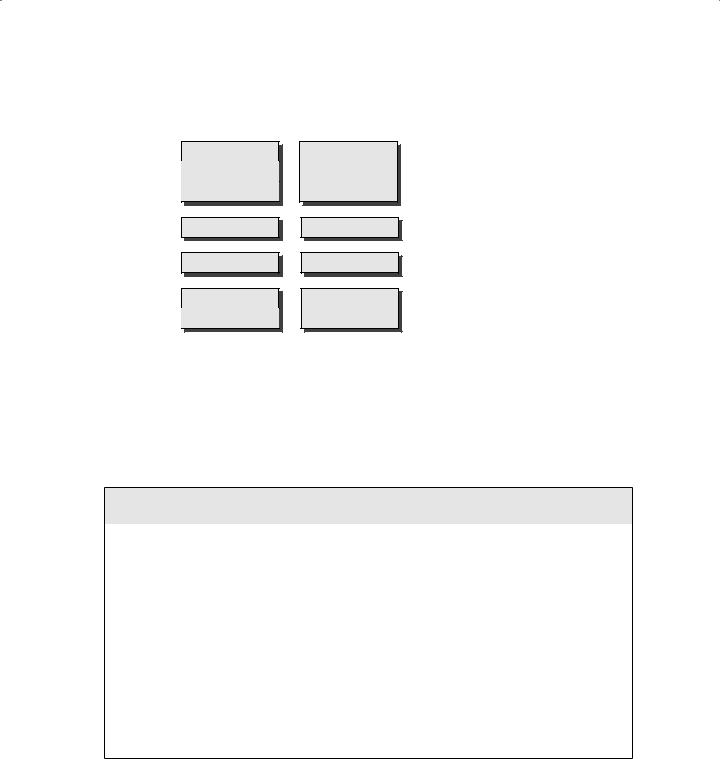
The TCP/IP model’s Application layer corresponds to layers 5, 6, and 7 of the OSI model. The TCP/IP model’s Host-to-Host layer corresponds to layer 4 from the OSI model. The TCP/ IP model's Internet layer corresponds to layer 3 from the OSI model. The TCP/IP model’s Network Access layer corresponds to layers 1 and 2 from the OSI model.
64 Chapter 3 ISO Model, Network Security, and Protocols
F I G U R E 3 . 5 Comparing the OSI model with the TCP/IP model
OSI Model
Application
Presentation
Session
Transport
Network
Data Link
Physical
TCP/IP Model
Process Application
Host-to-Host
Internet
Network Access
Communications and Network Security
Establishing security on a network involves more than just managing the OS and software. You must also address physical issues, including cabling, topology, and technology.
LANs vs. WANs
There are two basic types of networks: LANs and WANs. A local area network (LAN) is a selfenclosed network typically spanning a single floor or building. LANs usually employ lowto moderate-speed technologies. Wide area network (WAN) is the term usually assigned to the long-distance connections between geographically remote networks. WANs often employ high-speed connections, but they can also employ low-speed dial-up links as well as leased connection technologies.
WAN connections and communication links can include private circuit technologies and packetswitching technologies. Common private circuit technologies include dedicated or leased lines and PPP, SLIP, ISDN, and DSL connections. Packet-switching technologies include X.25, Frame Relay, asynchronous transfer mode (ATM), Synchronous Data Link Control (SDLC), and HighLevel Data Link Control (HDLC). Packet-switching technologies use virtual circuits instead of dedicated circuits. A virtual circuit is created only when needed, which makes for efficient use of the medium and is extremely cost effective.

Communications and Network Security |
65 |
Network Cabling
The type of connectivity media employed in a network is important to the network’s design, layout, and capabilities. Without the right cabling, a network may not be able to span your entire enterprise or it may not support the necessary traffic volume. Different types of network devices and technologies are used with different types of cabling. Each cable type has unique useful lengths, throughput rates, and connectivity requirements.
Coaxial Cable
Coaxial cable, also called coax, was a popular networking cable type used throughout the 1970s and 1980s. In the early 1990s, its use quickly declined due to the popularity of twistedpair wiring (explained in more detail later). Coaxial cable has a center core of copper wire surrounded by a layer of insulation, which is in turn surrounded by a conductive braided shielding and encased in a final insulation sheath.
The center copper core and the braided shielding layer act as two independent conductors, thus allowing two-way communications over a coaxial cable. The design of coaxial cable makes it fairly resistant to electromagnetic interference (EMI) and able to support high bandwidths (in comparison to other technologies of the time period), and it offers longer usable lengths than twisted-pair. It ultimately failed to retain its place as the popular networking cable technology due to twisted-pair’s much lower cost and ease of installation. Coaxial cable requires the use of segment terminators, whereas twisted-pair does not. Coaxial cable is bulkier and has a larger minimum arc radius than twisted-pair. (The arc radius is the minimum distance the cable can be bent before damaging the internal conductors.) Additionally, with the widespread deployment of switched networks, the issues of cable distance became moot due to the implementation of hierarchical wiring patterns.
There are two main types of coaxial cable: thinnet and thicknet. Thinnet, also known as 10Base2, was commonly used to connect systems to backbone trunks of thicknet cabling. Thinnet can span distances of 185 meters and provide throughput up to 10Mbps. Thicknet, also known as 10Base5, can span 500 meters and provide throughput up to 10Mbps.
Baseband and Broadband
The naming convention used to label most network cable technologies follows the syntax XXyyyyZZ. XX represents the maximum speed the cable type offers, such as 10Mbps for a 10Base2 cable. yyyy represents the baseband or broadband aspect of the cable, such as baseband for a 10Base2 cable. Baseband cables can transmit only a single signal at a time. Broadband cables can transmit multiple signals simultaneously. Most networking cables are baseband cables. However, when used in specific configurations, coaxial cable can be used as a broadband connection, such as with cable modems. ZZ either represents the maximum distance the cable can be used or acts as shorthand to represent the technology of the cable, such as the approximately 200 meters for 10Base2 cable (actually 185 meters, but it’s rounded up to 200), or T or TX for twisted-pair in 10Base-T or 100Base-TX. (Note that 100Base-TX is implemented using two CAT 5 UTP or STP cables, one issued for receiving, the other for transmitting.)

66 Chapter 3 ISO Model, Network Security, and Protocols
Table 3.1 shows the important characteristics for the most common network cabling types.
T A B L E 3 . 1 |
Important Characteristics for Common Network Cabling Types |
||||
|
|
|
|
|
|
|
|
|
Difficulty of |
Susceptibility |
|
Type |
Max Speed |
Distance |
Installation |
to EMI |
Cost |
|
|
|
|
|
|
10Base2 |
10Mbps |
185 m |
Medium |
Medium |
Medium |
10Base5 |
10Mbps |
500 m |
High |
Low |
High |
10Base-T |
10Mbps |
100 m |
Low |
High |
Very low |
(UTP) |
|
|
|
|
|
STP |
155Mbps |
100 m |
Medium |
Medium |
High |
100Base-T/ |
100Mbps |
100 m |
Low |
High |
Low |
100Base-TX |
|
|
|
|
|
1000Base-T |
1Gbps |
100 m |
Low |
High |
Medium |
Fiber-optic |
2Gbps |
2 k |
Very high |
None |
Very high |
|
|
|
|
|
|
Twisted-Pair
Twisted-pair cabling is extremely thin and flexible compared to coaxial cable. It is made up of four pairs of wires that are twisted around each other and then sheathed in a PVC insulator. If there is a metal foil wrapper around the wires underneath the external sheath, the wire is known as shielded twisted-pair (STP). The foil provides additional protection from external EMI.
Twisted-pair cabling without the foil is known as unshielded twisted-pair (UTP). UTP is most often referred to as just 10Base-T.
The wires that make up UTP and STP are small, thin copper wires that are twisted in pairs. The twisting of the wires provides protection from external radio frequencies and electric and magnetic interference and reduces crosstalk between pairs. Crosstalk occurs when data transmitted over one set of wires is picked up by another set of wires due to radiating electromagnetic fields produced by the electrical current. Each wire pair within the cable is twisted at a different rate (i.e., twists per inch); thus, the signals traveling over one pair of wires cannot cross over onto another pair of wires. The tighter the twist (the more twists per inch), the more resistant the cable is to internal and external interference and crosstalk and thus the capacity for throughput (that is, higher bandwidth) is greater.
There are several classes of UTP cabling. The various categories are created through the use of tighter twists of the wire pairs, variations in the quality of the conductor, and variations in the quality of the external shielding. Table 3.2 shows the UTP categories.

|
|
Communications and Network Security |
67 |
T A B L E 3 . 2 |
UTP Categories |
|
|
|
|
|
|
UTP Category |
Throughput |
Notes |
|
|
|
|
|
Cat 1 |
Voice only |
Not suitable for networks, but usable by modems |
|
Cat 2 |
4Mbps |
Not suitable for most networks, often employed for |
|
|
|
host-to-terminal connections on mainframes |
|
Cat 3 |
10Mbps |
Primarily used in 10Base-T Ethernet networks (offers |
|
|
|
only 4Mpbs when used on Token Ring networks) |
|
Cat 4 |
16Mbps |
Primarily used in Token Ring networks |
|
Cat 5 |
100Mbps |
Used in 100Base-TX, FDDI, and ATM networks |
|
Cat 6 |
155Mbps |
Used in high-speed networks |
|
Cat 7 |
1Gbps |
Used on gigabit-speed networks |
|
|
|
|
|
Conductors
The distance limitations of conductor-based network cabling is due to the resistance of the metal used as a conductor. Copper, the most popular conductor, is one of the best and least expensive room-temperature conductors available. However, it is resistant to the flow of electrons. This resistance results in a degradation of signal strength and quality over the length of the cable. The maximum length defined for each cable type indicates the point at which the level of degradation could begin to interfere with the efficient transmission of data. This degradation of the signal is known as attenuation. It is often possible to use a cable segment that is longer than the cable is rated for, but the number of errors and retransmissions will be increased over that cable segment, ultimately resulting in poor network performance. Attenuation is more pronounced as the speed of the transmission increases. It is recommended to use shorter cable lengths as the speed of the transmission increases.
Long cable lengths can often be supplemented through the use of repeaters or concentrators. A repeater is just a signal amplification device, much like the amplifier for your car or home stereo. The repeater boosts the signal strength of an incoming data stream and rebroadcasts it through its second port. A concentrator does the same thing except it has more than just two ports. However, the use of more than four repeaters in a row is discouraged (see the sidebar “3-4-5 Rule”).
An alternative to conductor-based network cabling is fiber-optic cable. Fiber-optic cables transmit pulses of light rather than electricity. This has the advantage of being extremely fast and near impervious to tapping. However, it is difficult to install and expensive; thus, the security and performance it offers comes at a steep price.

68 Chapter 3 ISO Model, Network Security, and Protocols
3-4-5 Rule
The 3-4-5 rule is used whenever Ethernet or other IEEE 802.3 shared-access networks are deployed in a tree topology (i.e., a central trunk with various splitting branches). This rule defines the number of repeaters/concentrators and segments that can be used in a network design. The rule states that between any two nodes (a node can be any type of processing entity, such as a server, client, router, etc.), there can be a maximum of five segments connected by four repeaters/concentrators and that only three of those five segments can be populated (i.e., have additional or other user, server, or networking device connections).
The 3-4-5 rule does not apply to switched networks.
Wireless
In addition to wire-based network connectivity media, we must include wireless connectivity. Wireless network interfaces are widely used as an alternative to running UTP cabling throughout a work area. Wireless networking is based on IEEE 802.11b and 802.11a standards.
802.11b devices can transmit data up to 11Mbps. 802.11a devices can transmit data up to 54Mbps. Wireless networking uses connection hubs that can support one to dozens of wireless NICs. The primary drawback of wireless networking is that the signals connecting the NICs to the hubs may not be encrypted. Virtual private networks (VPNs) or other traffic encryption mechanisms must be employed to provide security for the connections. A wireless link is more susceptible to eavesdropping because the signals can often be detected blocks away, whereas UTP cables require direct physical access to tap into the traffic.
LAN Technologies
There are three main types of local area network (LAN) technologies: Ethernet, Token Ring, and FDDI. There are a handful of other LAN technologies, but they are not as widely used as these three. Most of the differences between LAN technologies occurs at and below the Data Link layer.
Ethernet
Ethernet is a shared media LAN technology (also known as a broadcast technology). That means it allows numerous devices to communicate over the same medium but requires that each device take turns communicating and perform collision detection and avoidance. Ethernet employs broadcast and collision domains. A broadcast domain is a physical grouping of systems in which all of the systems in the group receive a broadcast sent by a single system in the group. A broadcast is a message transmitted to a specific address that indicates that all systems are the intended recipients.
A collision domain consists of groupings of systems within which a data collision occurs if two systems transmit simultaneously. A data collision takes place when two transmitted messages attempt to use the network medium at the same time. It causes one or both of the messages to be corrupted.

Communications and Network Security |
69 |
Ethernet can support full-duplex communications (i.e., full two-way) and usually employs coaxial or twisted-pair cabling. Ethernet is most often deployed on star or bus topologies. Ethernet is based on the IEEE 802.3 standard. Individual units of Ethernet data are called frames.
Token Ring
Token Ring employs a token-passing mechanism to control which systems can transmit data over the network medium. The token travels in a logical loop among all members of the LAN. Token Ring can be employed on ring or star network topologies. It is rarely used today due to its performance limitations, higher cost compared to Ethernet, and increased difficulty in deployment and management.
Fiber Distributed Data Interface (FDDI)
Fiber Distributed Data Interface (FDDI) is a high-speed token-passing technology that employs two rings with traffic flowing in opposite directions. FDDI is often used as a backbone for large enterprise networks. Its dual-ring design allows for self-healing by removing the failed segment from the loop and creating a single loop out of the remaining inner and outer ring portions. FDDI is expensive but was often used in campus environments before Fast Ethernet and Gigabit Ethernet were developed.
Sub-technologies
Most networks comprise numerous technologies rather than a single technology. For example, Ethernet is not just a single technology but a superset of sub-technologies that support its common and expected activity and behavior. Ethernet includes the technologies of digital communications, synchronous communications, and baseband communications, and it supports broadcast, multicast, and unicast communications and Carrier-Sense Multiple Access with Collision Detection (CSMA/CD). Many of the LAN technologies, such as Ethernet, Token Ring, and FDDI, may include many of the sub-technologies described in the following sections.
Analog and Digital
One sub-technology is the mechanism used to actually transmit communication signals over a physical medium, such as a cable. There are two types: analog and digital. Analog communications occur with a continuous signal that varies in frequency, amplitude, phase, voltage, and so on. The variances in the continuous signal produce a wave shape (as opposed to the square shape of a digital signal). The actual communication occurs by variances in the constant signal. Digital communications occur through the use of a discontinuous electrical signal and a state change or on-off pulses.
Synchronous and Asynchronous
Some communications are synchronized with some sort of clock or timing activity. Communications are either synchronous or asynchronous. Synchronous communications rely upon a timing or clocking mechanism based upon either an independent clock or a time stamp embedded in the data stream. Synchronous communications are typically able to support very high rates of data transfer. Asynchronous communications rely upon a stop and start delimiter bit to manage transmission of data. Due to the use of delimiter bits and the stop and start nature of its transmission, asynchronous communication is best suited for smaller amounts of data. Standard modems over normal telephone lines are good examples of asynchronous communication.

70 Chapter 3 ISO Model, Network Security, and Protocols
Baseband and Broadband
How many communications can occur simultaneously over a cable segment depends on whether you use baseband technology or broadband technology. Baseband technology can support only a single communication channel. It uses a direct current applied to the cable. A current that is on represents the binary signal of 1, and a current that is off represents the binary signal of 0. Ethernet is a baseband technology. Broadband technology can support multiple simultaneous signals. Broadband uses frequency modulation to support numerous channels, each supporting a distinct communication session. Broadband is suitable for high-throughput rates, especially when several channels are multiplexed. Cable television and cable modems, ISDN, DSL, T1, and T3 are examples of broadband technologies.
Broadcast, Multicast, and Unicast
Another sub-technology determines how many destinations a single transmission can reach. The options are broadcast, multicast, and unicast. A broadcast technology supports communications to all possible recipients. A multicast technology supports communications to multiple specific recipients. A unicast technology supports only a single communication to a specific recipient.
LAN Media Access
Finally, there are at least five LAN media access technologies that are used to avoid or prevent transmission collisions.
Carrier Sense Multiple Access (CSMA) The LAN media access technology that performs communications using the following steps:
1.The host listens to the LAN media to determine if it is in use.
2.If the LAN media is not currently being used, the host transmits its communication.
3.The host waits for an acknowledgment.
4.If no acknowledgment is received after a timeout period, the host starts over at step 1.
Carrier-Sense Multiple Access with Collision Avoidance (CSMA/CA) The LAN media access technology that performs communications using the following steps:
1.The host has two connections to the LAN media: inbound and outbound. The host listens on the inbound connection to determine if the LAN media is in use.
2.If the LAN media is not currently being used, the host requests permission to transmit.
3.If permission is not granted after a timeout period, the host starts over at step 1.
4.If permission is granted, the host transmits its communication over the outbound connection.
5.The host waits for an acknowledgment.
6.If no acknowledgment is received after a timeout period, the host starts over at step 1. AppleTalk is a specific example of a CSMA/CA protocol.