

146 Carbon, Graphite, Diamond, and Fullerenes
All |
of this |
is valuable |
information |
which |
can |
be |
of great |
help. |
Yet, |
it |
|||||||||
must be treated with caution |
since, in spite of all the |
progress |
|
in thermody- |
|
||||||||||||||
namic |
analysis, |
the complexity |
of many reactions |
in the CVD |
of carbon, and |
||||||||||||||
the fact that |
these |
calculations |
are based |
on chemical |
equilibrium which |
is |
|||||||||||||
rarely |
attained |
in |
CVD |
reactions, |
make |
predictions |
|
relying |
on thermody- |
|
|||||||||
namic |
calculations |
alone |
still |
questionable. |
|
|
|
|
|
|
|
|
|||||||
Itfollowsthat, |
in orderto |
provide |
a reliable |
and |
balanced |
investigation, |
|
||||||||||||
it is preferable |
to combine |
the |
theoretical |
calculations |
|
with an experimental |
|
||||||||||||
program. |
Fortunately, |
carbon |
deposition |
experiments |
are relatively |
easy to |
|||||||||||||
design |
and carry out without the need |
for expensive |
equipment, |
and |
results |
||||||||||||||
can usually |
be obtained |
quickly |
and |
reliably. |
|
|
|
|
|
|
|
|
|||||||
2.4CVD Reactions for the Deposition of Pyrolytic Graphite
|
The |
CVD |
reactions |
to |
deposit |
|
pyrolytic |
graphite |
are |
based |
on |
the |
||||||||||
thermal |
decomposition |
|
(pyrolysis) |
|
of |
hydrocarbons. |
|
The |
most common |
|||||||||||||
precursor |
is |
methane |
(CH,), which |
|
is |
generally |
pyrolyzed |
at |
1100°C or |
|||||||||||||
above, over a wide range |
of pressure |
from about |
100 Pa (0.001 |
atm) to 1O5 |
||||||||||||||||||
Pa (1 atm). |
The |
reaction |
in |
a simplified |
form |
is as follows:tl)[lO)tll) |
|
|
||||||||||||||
Eq.(1) |
|
|
|
CH, |
|
+ |
C + 2H, |
|
|
|
|
|
|
|
|
|
|
|
|
|
||
|
Other |
common |
|
precursors |
|
are |
ethylene |
(C&H,) |
and |
acetylene |
||||||||||||
(&HA |
.tlltl*l |
Acetylene |
can also be decomposed |
at lower |
temperature |
|
(300 |
|||||||||||||||
- 750°C) and at pressures |
up to 1 atm, in the presence |
of a nickel |
catalyst.tl*) |
|||||||||||||||||||
Another |
common |
precursor |
is propylene |
(C,H,) |
which |
decomposes |
in the |
|||||||||||||||
1000 |
- 1400°C |
temperature |
range |
at low pressure |
(- |
1.3 x lo4 |
Pa or |
100 |
||||||||||||||
Torr) |
.t13) |
|
|
|
|
|
|
|
|
|
|
|
|
|
|
|
|
|
|
|
|
|
|
The |
activation |
energies |
for |
the |
decomposition |
|
of |
these |
precursor |
||||||||||||
gases still are not accurately |
known |
and |
show |
a considerable |
scatter. |
The |
||||||||||||||||
reported |
values |
|
are |
as follows: |
|
|
|
|
|
|
|
|
|
|
|
|
|
|||||
|
|
|
|
|
Methane |
|
78 - 106 kcal/g.mole |
|
|
|
|
|
|
|||||||||
|
|
|
|
|
Ethane |
|
60 - 86 kcal/g.mole |
|
|
|
|
|
|
|
||||||||
|
|
|
|
|
Acetylene |
30 |
- 50 kcal/g-mole |
|
|
|
|
|
|
|
||||||||
Deposition Mechanism: The pyrolysis of a hydrocarbon, such as shown in reaction equation (l), is actually a series of more complex reactions involving molecules of gradually increasing size. A possible
Pyrolytic Graphite 147
mechanism of deposition of pyrolytic graphite is deduced from a series of
experiments carried out in the apparatus shown in Fig. 7.1 .f5i
C”4 |
Pressure |
Gas |
|
Recorder |
Chromatograph |
||
I |
|||
|
|
Pressure
Recorder
Exhaust 4 |
M |
|
|
Vacuum |
Needle |
Li uid Valve |
|
Pump |
N, ‘t rap |
Figure 7.1. Schematic of experimental apparatus for the productionof pyrolytic graphite.f5]
in |
this |
study, |
|
a spectrographic |
analysis |
of |
the by-products |
of |
the |
||||||||||||
decomposition |
|
of |
methane |
revealed |
the |
presence |
of |
large |
|
amounts |
of |
||||||||||
acetylene, |
ethylene, |
and |
benzene, |
plus |
a variety |
of compounds |
consisting |
||||||||||||||
mostly |
of |
the |
poiyaromatic |
hydrocarbons |
|
(PAH) |
such |
as |
naphthaiene, |
||||||||||||
anthracene, |
|
phenantrene, |
acenaphthyiene, |
|
pyrene, |
and fiuoranthene, |
in |
||||||||||||||
addition |
to |
the |
deposited |
pyrolytic |
graphite. |
Some |
of |
these |
|
compounds |
|||||||||||
form the soot and tar-like |
deposits |
which |
are |
often |
observed |
on the |
wail |
of |
|||||||||||||
CVD reactors |
|
during |
carbon |
deposition. |
|
|
|
|
|
|
|
|
|
|
|
||||||
it is generally |
agreed |
that the following |
simplified |
deposition |
sequence |
||||||||||||||||
is taking |
piace:[51[14] |
|
|
|
|
|
|
|
|
|
|
|
|
|
|
|
|||||
Methane -+ Benzene ---, Poiyaromatic hydrocarbons + Carbon
148 |
Carbon, |
Graphite, |
Diamond, |
and |
Fuiierenes |
|
|
|
|
|||||||||
2.5 |
Deposition |
Systems |
and Apparatus |
|
|
|
|
|
||||||||||
|
A common CVD apparatus for the deposition of pyrolytic graphite is the |
|||||||||||||||||
so-called |
cold-wail reactor. This reactor does not require a furnace since |
the |
||||||||||||||||
substrate |
to |
be coated |
is heated |
directly, |
usually |
by induction |
heating. |
|
||||||||||
|
The |
decomposition |
|
reactions |
for the deposition |
of pyrolytic |
graphite |
are |
||||||||||
endothermic, |
|
i.e., they |
absorb |
heat. |
As |
a result, |
deposition |
takes place |
||||||||||
preferentially |
on thesurfaceswhere |
|
the temperature |
isthe |
highest, |
in this case |
||||||||||||
the substrate, |
|
while the coolerwails |
of the reactor remain essentially |
uncoated. |
||||||||||||||
|
A |
simple |
laboratory |
type |
reactor for |
pyrolytic-graphite |
deposition |
is |
||||||||||
shown |
in Fig. 7.2.R The substrate |
is amoided-graphite |
diskwhich |
is rotated |
||||||||||||||
to improve |
deposition uniformity. |
|
it is heated by a high-frequency |
(450 kHz) |
||||||||||||||
induction |
coil and deposition |
occurs at low pressure |
(500 Pa). Temperature |
|||||||||||||||
is monitored |
and |
controlled |
by a sheathed |
thermocouple |
and |
corroborated |
||||||||||||
by an |
optical |
|
pyrometer. |
|
|
|
|
|
|
|
|
|
|
|
|
|||
|
Production |
systems |
of a similar |
basic |
design |
now |
reach |
considerable |
||||||||||
size, |
with |
CVD furnaces |
|
1.2 m in diameter |
and over 2 m high commercially |
|||||||||||||
available. |
|
|
|
|
|
|
|
|
|
|
|
|
|
|
|
|
||
cH44---l“’
|
I I |
Quartz |
|
|
|
Optical |
/ |
Reactor |
|
Tube |
|
Pyrometer ~ |
|
|
|
|
|
8 |
|
|
; |
|
|
Pressure |
|
|
Recorder |
|
|
Exhaust
Thermocouple -
Figure 7.2. Schematic of a cold-wail reactor for the production of pyrolytic graphite.t31
|
|
|
|
|
|
|
|
|
|
|
Pyrolytic |
Graphite |
149 |
||||
2.6 |
Chemical Vapor Infiltration |
(CVI) |
|
|
|
|
|
|
|
||||||||
|
Chemical |
vapor |
infiltration |
(CM) |
is a special |
CVD process |
in which the |
||||||||||
gaseous reactant |
infiltrates |
a porous |
material |
such |
as |
an inorganic |
open |
||||||||||
foam |
or a fibrous |
mat or weave. |
The |
deposition |
occurs |
on the fiber |
(or the |
||||||||||
foam), |
and the |
structure is gradually |
densified |
to form |
a composite.t15] |
||||||||||||
|
CVI has the same chemistry |
and thermodynamics |
|
as conventional |
|||||||||||||
CVD, |
but the |
kinetics |
is different |
since |
the reactants |
have |
to diffuse |
inward |
|||||||||
through |
the |
porous |
structure |
and |
the |
by-products |
of the |
reaction have to |
|||||||||
diffuse |
out.t16j The process is used |
extensively |
in the |
production |
of carbon- |
||||||||||||
carbon |
materials, |
reviewed |
in Ch. |
9.n7] |
|
|
|
|
|
|
|
||||||
2.7Fluidized-Bed CVD
Fluidized-bed |
|
CVD is a special |
technique |
which |
is used |
primarily |
in |
|||||||||||||||
coating |
particles |
such |
as |
nuclear |
fuel. |
A flowing |
gas imparts |
quasi-fluid |
|
|||||||||||||
properties |
to the |
|
particles. |
|
Fig. |
7.3 |
shows |
a typical |
fluidized-bed |
CVD |
||||||||||||
reactor.f3j |
|
|
|
|
|
|
|
|
|
|
|
|
|
|
|
|
|
|
|
|
|
|
The |
fluidizing |
|
gas is usually |
methane, |
helium, |
or another non-reactive |
|
|||||||||||||||
gas. Factorsto |
considerto |
obtain |
properfluidization |
are the density and size |
||||||||||||||||||
of the particles |
to be coated, |
and |
the |
velocity, |
|
density, |
and |
viscosity |
of the |
|||||||||||||
gases.t’st |
If the |
velocity |
is too |
low, |
the particles |
will fall into the gas inlet; |
if |
|||||||||||||||
it is too |
high, they |
will be blown |
out |
of the |
bed. |
Heavy |
or large |
objects |
may |
|||||||||||||
require |
suspension |
|
in the |
bed. |
|
|
|
|
|
|
|
|
|
|
|
|
|
|
||||
The |
gas velocity, |
V,, |
is given |
by the |
following |
relationship: |
|
|
||||||||||||||
|
|
|
V, |
= d*(p,- |
p,)G/1650~ |
|
|
|
[for |
dV, ps/~ |
401 |
|
|
|||||||||
where: |
|
|
d = particle |
diameter |
|
|
|
|
|
|
|
|
|
|
|
|||||||
|
|
|
pp = particle |
density |
|
|
|
|
|
|
|
|
|
|
|
|||||||
|
|
|
ps = gas density |
|
|
|
|
|
|
|
|
|
|
|
|
|
||||||
|
|
|
G |
= acceleration |
of gravity |
|
|
|
|
|
|
|
|
|
||||||||
|
|
|
V, |
= superficial |
|
gas |
velocity |
|
|
|
|
|
|
|
|
|||||||
|
|
|
I-( = gas viscosity |
|
|
|
|
|
|
|
|
|
|
|
|
|
||||||
The |
major |
applications |
|
of pyrolytic |
carbon |
deposited |
by fluidized |
bed |
||||||||||||||
are found |
in the |
production |
of biomedical |
components |
such |
as heart valves |
||||||||||||||||
and in |
the coating |
of |
uranium |
carbide |
and |
thorium |
carbide |
nuclear-fuel |
|
|||||||||||||
150 Carbon, |
Graphite, |
Diamond, |
and |
Fullerenes |
|
|
|
|
|
|||
particles |
for high |
temperature gas-cooled |
reactors, |
for |
the purpose |
of |
||||||
containing |
the |
products of nuclear fission. |
The carbon |
is obtained from the |
||||||||
decomposition |
of |
propane |
(C,H,) |
or propylene |
(C,H,) |
at |
135O”C, |
or |
of |
|||
methane |
(CH,) |
at 1800°C.[1] Its structure is usually |
isotropic |
(see Sec. |
3.5). |
|||||||
View Port
Disentraiment
Mass
Flow Meter
Figure 7.3. Schematicof afluidized-bed CVD reactorforthe deposition of pyrolytic graphite.f3]
Pyrolytic Graphite |
151 |
2.8Plasma CVD
The |
deposition |
of graphite |
can |
also |
be obtained |
by plasma |
CVD, with |
||||||||
the following |
characteristics:tlQ] |
|
|
|
|
|
|
|
|
|
|
||||
. Gases: propylene-argon |
or methane-argon |
|
|
|
|
|
|||||||||
. |
Plasma: |
radio |
frequency |
(RF) |
at 0.5 MHz |
|
|
|
|
|
|||||
. Pressure: cl 300 Pa |
|
|
|
|
|
|
|
|
|
|
|||||
. Temperature: |
300 - 500% |
|
|
|
|
|
|
|
|
||||||
In a plasma-activated |
reaction, |
the substrate |
temperature |
can |
be |
||||||||||
considerably |
lower |
than |
in |
thermal |
CVD. This |
|
allows |
the |
coating |
of |
|||||
thermally |
sensitive |
materials. |
The |
characteristics, |
|
and properties |
of |
the |
|||||||
coating are |
similar |
to those |
of coatings |
|
deposited |
at higher temperatures |
|||||||||
(>1ooo”c). |
|
|
|
|
|
|
|
|
|
|
|
|
|
|
|
Plasma |
activation |
is |
also used |
extensively |
|
in the |
deposition |
of |
|||||||
polycrystalline |
diamond |
and |
diamond-like |
carbon |
(DLC). |
It is reviewed |
in |
||||||||
more detail |
in Chs. |
13 and 14. |
|
|
|
|
|
|
|
|
|
|
|||
3.0 STRUCTURE OF PYROLYTIC GRAPHITE
3.1The Various Structures of Pyrolytic Graphite
Pyrolytic |
graphite |
is an aggregate |
of graphite crystallites |
which |
have |
|||||||||||||
dimensions |
(LJ that may |
reach |
several |
hundred |
nm (see Ch. 3, Sec. |
2). |
It |
|||||||||||
has a turbostratic |
structure, |
usually |
with |
many warped |
basal |
planes, |
lattice |
|||||||||||
defects, |
and |
crystallite |
imperfections. |
|
|
|
|
|
|
|
|
|
||||||
Within |
the aggregate, |
the |
crystallites |
have |
various |
degrees |
of |
orien- |
||||||||||
tation. When |
they |
are |
essentially |
parallel |
to each |
other, |
the nature and the |
|||||||||||
properties |
of the deposit |
closely |
match that of the ideal |
graphite |
crystal. |
|
||||||||||||
The |
structure |
of a pyrolytic |
graphite |
deposit |
can be either |
columnar, |
||||||||||||
laminar, |
or |
|
isotropic, |
depending |
on the deposition |
conditions |
such |
as |
||||||||||
temperature, |
|
pressure, |
and |
composition |
|
of the input |
gases.[11[101[14][20]It is |
|||||||||||
possible |
to |
|
obtain |
the |
desired |
structure |
by the |
proper |
control |
of |
these |
|||||||
deposition |
parameters. |
|
|
|
|
|
|
|
|
|
|
|
|
|
|
|||
3.2Columnar and Laminar Structures
Columnar Structure. The |
columnar structure of pyrolytic |
graphite |
is |
shown in Fig. 7.4. The crystallites |
are deposited with the basal |
planes |
(ab |

152 Carbon, Graphite, Diamond, |
and Fullerenes |
||||
directions) |
essentially |
parallel to |
the |
deposition suriace. Their structure |
|
tends |
to be columnar |
(cone-like) |
as a result of uninterrupted grain growth |
||
toward |
the |
reactant source. |
|
|
|
Effect |
of Substrate |
Geometry. |
The smoothness |
of the substrate is |
|||||||||||||||||
a very critical factor. Fig. 7.5 shows schematically |
the growth of the graphite |
||||||||||||||||||||
deposit |
above |
a convex |
surface |
defect of the substrate |
such as a surface |
||||||||||||||||
asperity |
or a dust particle. |
The deposit tends to magnify |
|
any such surface |
|||||||||||||||||
imperfection |
and, to obtain |
a uniform |
pyrolytic |
graphite growth, |
a perfectly |
||||||||||||||||
smooth |
and clean surface |
is necessary |
.[11) |
|
|
|
|
|
|
|
|
||||||||||
Continuous |
N ucleation. |
The structure is also often dependent |
on the |
||||||||||||||||||
thickness |
of the |
deposit. |
For |
instance, |
the |
grain size |
|
increases |
as the |
||||||||||||
thickness |
increases |
and |
the |
columnar-grain |
|
structure |
becomes |
|
more |
||||||||||||
pronounced |
as the film |
becomes |
thicker. |
Such |
large columnar |
structures |
|||||||||||||||
are usually |
undesirable |
as the |
deleterious |
effects |
of |
grain growth |
and |
||||||||||||||
columnar |
formation can be considerable, |
|
causing structural failure |
and the |
|||||||||||||||||
rapid diffusion |
of impurities |
along grain |
boundaries. |
|
|
|
|
|
|
||||||||||||
Large |
grain |
size can be avoided by continuously |
adding growth |
sites, |
|||||||||||||||||
where |
new |
columnar |
growth |
can |
be |
generated. |
This |
effect |
is |
shown |
|||||||||||
schematically |
in |
Fig. |
7.6. |
These new growth sites originate from soot |
|||||||||||||||||
particles, |
which |
are |
formed |
in |
the |
gas-phase |
when |
the pressure |
and |
||||||||||||
supersaturation |
|
are above |
a certain |
level.[11][14) |
|
|
|
|
|
|
|||||||||||
Pyrolytic Graphite 153
De osition |
|
5 one |
I |
Substrate |
Substrate |
Defect |
|
Figure7.5. Effectofsubstratedefectondepositedstructureof |
pyrolyticgraphite.[“l |
Deposition Zone
Pyrolytic
Graphite
Deposit
Gas-phase
Nucleated
Impurity
Substrate
Figure 7.6. Effect of gas-phase nucleated impurities on deposited structure of pyrolytic graphite.[“]

154 |
Carbon, Graphite, Diamond, and Fullerenes |
|
|||||||
|
Laminar Structure. |
The |
laminar |
structure |
of |
pyrolytic graphite |
|||
consists |
of essentially parallel |
layers (or concentric |
shells if deposited on a |
||||||
particle |
or fiber). |
It is shown |
|
in Fig. 7.7. |
|
|
|
||
|
Both columnar and laminar |
structures |
are optically |
active to polarized |
|||||
light |
and usually |
have similar |
physical properties.[10)[14] |
||||||
Figure 7.7. |
Laminar |
structure |
of pyrolytic graphite, deposited |
on carbon filament |
(Photograph |
courtesy |
of Jack |
Chin, La Costa, CA.) |
|
3.3Isotropic Structure
The other type of pyrolytic |
structure, |
isotropic |
carbon, |
has |
little |
||||||
graphitic |
characteristic and essentially no optical |
activity .It is composed |
of |
||||||||
very fine grains without observable |
orientation |
and for this reason, |
it |
is |
|||||||
known |
as isotropic |
carbon |
rather than isotropic graphite. |
It is often obtained |
|||||||
in fluidized-bed deposition, |
possibly |
due to continuous surface regeneration |
|||||||||
by the |
mechanical |
rubbing action |
of the |
bed. |
An |
isotropic |
structure, |
||||
observed |
by transmission |
electron |
microscopy, |
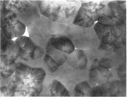
is shown in Fig. 7.8.[21) |
|
||||||
Pyrolytlc Graphite 155
Figure 7.8. High-density |
(- 2.0 g/cm3) isotropic |
structure |
of pyrolytic carbon, |
||
observed |
by transmission |
electron microscopy. |
Viewing |
plane is parallel to |
|
deposition |
plane (x= 23,600). (PhotographcourtesyofJo |
LoKaae, Genera/Atomics, |
|||
San Diego, |
CAo) |
|
|
|
|
3.4Effect of Deposition Parameters
Effect of Pressure. Pyrolytic-graphite coatings with more uniformity I
better coverage, and improved quality are generally obtained at low deposition
pressure. Pressure controls the thickness of the surface boundary layer and consequently the degree of diffusion. By operating at low pressure, the
diffusion process can be minimized and surface kinetics becomes rate-
controlling.[3] |
Low-pressure |
deposition tends to be isotropic. |
|||
At higher pressure (i.e., atmospheric) |
' the reactant gas must be diluted |
||||
with an non-reactive gas such as hydrogen |
or argon to prevent uncontrolled |
||||
vapor-phase |
precipitation, |
while |
generally |
no dilution |
is necessary at low |
pressure. However, atmospheric |
pressure reactors are simpler and cheaper , |
||||
and, with proper control of the deposition parameters, |
satisfactory deposits |
||||
can be obtained. |
|
|
|
|
|