

Flow Cytometry - First Principles (Second Edition)
.pdfInstrumentation |
17 |
Fig. 3.1. Cells ¯owing past illuminating beams of di¨erent pro®les. A beam with an elliptical pro®le (lower beam) allows cells to pass into and out of the beam quickly (avoiding the coincidence of two cells in the beam at the same time). In addition, it provides more equal illumination if cells stray from the center of the beam. The small circular beam at the top does not illuminate cells equally if they are at the edge of the stream core. The larger circular beam (in the middle) illuminates cells equally, but often includes multiple cells in the beam at the same time.
thus illuminating cells more-or-less identically even if they stray from the exact center of the beam; but at the same time this elliptical pro- ®le can provide temporal resolution between cells, illuminating only one at a time as they pass one by one into and out of the beam in its narrow dimension. The narrower the beam is, the more quickly will a cell pass through itÐgiving opportunity for the signal from that cell to drop o¨ before the start of the signal from the next cell in line and avoiding the coincidence of two cells in the beam simultaneously. In
18 |
Flow Cytometry |
multilaser systems, each beam of light is focused in a similar way but at di¨erent points along the stream; a cell moves through each beam in sequence.
CENTERING CELLS IN THE ILLUMINATING BEAM
The ¯uidics in a ¯ow cytometer are likely to be ignored until they go wrong. If they go wrong disastrously, they can make a terrible mess. If they go wrong with subtlety, they may turn a good experiment into artifactual nonsense without anyone ever noticing. On the assumption that the more disastrous problems can be solved by a combination of plumbing and mopping (both essential skills for ¯ow cytometrists), I will concentrate on the more subtle aspects of ¯uid control. Nevertheless, the potential hazard of working at the same time with volumes of water and with a high-voltage source should never be far from the mind of anyone working with a water-cooled laser or with a sorting cytometer with high-voltage stream de¯ection plates.
The ¯ow on a ¯ow cytometer begins (Fig. 3.2) at a reservoir of liquid, called the sheath ¯uid. Sheath ¯uid provides the supporting vehicle for directing cells through the laser beam. The sheath ¯uid reservoir is pressurized, usually with pumped room air, to drive the sheath ¯uid through a ®lter to remove extraneous particles and then through plastic tubing to the illumination point. This sheath stream is usually bu¨er of a composition that is appropriate to the types of particles being analyzed. For leukocytes or other mammalian cells, this usually means some sort of phosphate-bu¨ered saline solution. Other cells or other particles may have other preferences.
Di¨erent instruments employ di¨erent strategies for getting the sample with suspended cells into the sheath stream in the cytometer. Some instruments require cells to be in small test tubes that form a tight seal around an O-ring on a manifold. The manifold delivers air to the test tube, thus pushing the suspended cells up out of the test tube and through a plastic line to the sheath stream. Other instruments use a motor-driven syringe to remove a volume of sample and then inject it slowly into the cytometer. Depending on the instrument, there may be a greater or lesser degree of operator control over the rate of ¯ow. The amount of pressure driving the sample through the system will a¨ect the uniformity of alignment between the cells and

Instrumentation |
19 |
Fig. 3.2. The ¯uidics system, with air pressure pushing both the sample (with suspended cells) and the sheath ¯uid into the ¯ow cell.
the illuminating laser beam as the cells move through the cytometer. Low pressure is less likely to cause perturbation of the stream pro®le and of the position of the cells within that stream. Empirically, if increasing the pressure on the sample causes undue broadening or wavering of signals, the pressure is probably excessive.
If cells ¯ow too slowly through the cytometer, people start to make bad jokes about how microscopes cost less and are quicker. Because increasing the pressure may not be possible and, even if it is, is probably only a good idea within reasonable limits, the best way of getting cells to ¯ow at reasonably fast rates is simply to make up the original sample with cells at a reasonably high concentration. A million cells per milliliter is often about right; 105 cells per milliliter is beginning to be low enough to test one's patience; 104 cells per milliliter is probably too low a concentration to be worth analyzing.
If you have few cells, make them up in a small volume (you will know how small a volume your system can handle). If the cells end

20 |
|
|
|
|
|
Flow Cytometry |
|
|
|
|
|
|
|
|
|
|
|
|
|
|
|
|
|
|
|
|
|
|
|
|
|
|
|
|
|
|
|
|
|
|
|
|
|
|
|
|
|
|
|
|
|
|
|
|
|
|
|
|
|
|
|
|
|
|
|
|
|
|
|
|
|
|
|
|
|
|
|
|
|
|
|
|
|
|
|
|
|
|
|
|
|
|
|
|
|
Fig. 3.3. The probability of an event recorded by the ¯ow cytometer as a single ``cell'' actually resulting from more than one cell coinciding in the laser beam. For this model, the laser beam was considered to be 30 mm high and the stream ¯owing at 10 m per second.
up being too concentrated, they may ¯ow too fastÐbut you can always dilute them on the spot and run the sample again. You may wonder why too rapid a ¯ow is a source of problems. Faster seems as if it should always be better (especially around 5:00 pm). However, if cells are too close together as they ¯ow through the laser beam, there may be di½culty separating their signals: A second cell may arrive in the illuminating beam before the preceding cell has emerged, and they will be measured together as if they were a single particle (with double the intensity). Figure 3.3 gives an indication of the probability of cells coinciding in the laser beam at di¨erent ¯ow rates. Most cytometers seem to be quite happy looking at particles that are ¯owing at a rate of about 1000 particles per second.
Aside from concentration, another problem with samples is that the particles may be the wrong size. If they are too small, they may not be distinguishable from noise; nevertheless, bacteria and picoplankton and other bits and pieces of about 1 mm diameter or smaller are analyzable in at least some well-tuned cytometers. If the particles are too large, however, they will obstruct ¯ow. If the ¯uid system is fully clogged, it may be di½cult to get things ¯owing again; if it is only partially clogged, cells may ¯ow but that critical alignment
Instrumentation |
21 |
between stream and light beam may be skewed, thus causing artifactual signals. Most experienced ¯ow cytometrists recommend ®l- tering any samples that are likely to contain large or clumped material before attempting to run them through the instrument. Nylon mesh of speci®ed pore size works well (35 mm mesh is appropriate for most applications).
The exact size of particle that will be large enough to cause obstruction depends primarily on the diameter of the ori®ce of the nozzle or ¯ow cell being used (usually between 50 and 250 mm). This brings us to the next stop downstream in our following of the ¯ow in this ¯ow cytometer. The terms nozzle, ¯ow cell, and ¯ow chamber derive from di¨erent engineering designs for the best way of delivering cells into the sheath ¯uid and thence to the analysis point where they are illuminated by the light. What we require is a method for keeping the cells in the center of the ¯uid stream so that they will pass through the center of the focused light beam and be uniformly illuminated. The ¯ow chamber is the place in the cytometer where the cells from the sample join the ¯uid from the sheath reservoir. Within the ¯ow chamber, the sample is injected into the center of the sheath stream; the combined sample and sheath streams are then accelerated as they move through a narrowing channel. This acceleration is critical to the precise alignment of cells, one at a time, in the laser beam. References at the end of this chapter will direct interested readers to mathematical discussion of the ¯uid mechanics related to this subject. For our purposes here, it will be enough to note that, as a result of considerations pertaining to laminar ¯ow through a narrowing path, the sample with its suspended cells, after injection into the center of the sheath stream, will remain in a central core as it ¯ows within the sheath stream out through the ¯ow chamber.
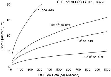
The technical term for this is hydrodynamic focusing; ¯ow of a sample stream within the center core of a sheath stream is called coaxial ¯ow. The exact diameter of that central sample core within the sheath stream is related to, among other things, the rate at which the sample is injected into the sheath stream; a 100 mm sheath stream may, depending on sample injection velocity, have a core width of perhaps 5±20 mm (Fig. 3.4). Because hydrodynamic focusing tends to con®ne the cell sample to this central core, there is little mixing of sample with sheath ¯uid (but di¨usion of small molecules will occur). The reason that this type of coaxial sample ¯ow suits ¯ow cytometry
22 |
|
|
|
Flow Cytometry |
|||||||||||||
|
|
|
|
|
|
|
|
|
|
|
|
|
|
|
|
|
|
|
|
|
|
|
|
|
|
|
|
|
|
|
|
|
|
|
|
|
|
|
|
|
|
|
|
|
|
|
|
|
|
|
|
|
|
|
|
|
|
|
|
|
|
|
|
|
|
|
|
|
|
|
|
|
|
|
|
|
|
|
|
|
|
|
|
|
|
|
|
|
|
|
|
|
|
|
|
|
|
|
|
|
|
|
|
|
|
|
|
|
|
|
|
|
|
|
|
|
|
|
|
|
|
|
|
|
|
|
|
|
|
|
|
|
|
|
|
|
|
|
|
|
|
|
|
|
|
|
|
|
|
|
|
|
|
|
|
|
|
|
|
|
|
|
|
|
|
|
|
|
|
|
|
|
|
|
|
|
|
|
|
|
|
|
|
|
|
|
|
|
|
|
|
|
|
|
|
|
|
|
|
|
|
|
|
|
|
|
|
|
|
|
|
|
|
|
|
|
|
|
|
|
|
|
|
|
|
|
|
|
|
|
|
|
|
|
|
|
|
|
|
|
|
|
|
|
|
|
|
|
|
|
|
|
|
|
|
|
|
|
|
|
|
|
|
|
|
|
|
|
|
|
|
|
|
|
|
|
|
|
|
|
|
|
|
|
|
|
|
|
|
|
|
|
|
|
|
|
|
|
|
|
|
|
|
|
|
Fig. 3.4. When cells are pushed through the cytometer at faster rates, the sample core widens. Use of a more concentrated cell suspension allows a faster ¯ow rate while maintaining a narrow core.
is that a nozzle or ¯ow cell with a relatively wide ori®ce (50±250 mm) can be used to avoid blockage; the particles to be analyzed are nevertheless maintained in alignment in the narrow (say 5±20 mm) core so that they progress in single ®le down the center of the stream through the laser beam. This ensures uniform illumination as long as the central core is narrow and the illuminating beam is focused at the center of the sheath stream. It also ensures that, because the cells are stretched out at a distance from each other as rare beads along a gold chain, for the most part one particle is illuminated at a time.
We are now in a position to understand why radical changes in the rate at which the sample is pushed through the ¯ow cell will cause changes in the resulting light signals. Changes in sample injection rate cause changes in the diameter of the core; when the size of the core increases, particles are no longer so tightly restricted in their position as they ¯ow past the light beam, and illumination will be less uniform (Fig. 3.5). The size of the core often has critical impact in this way on DNA applications where precise analysis is important and nonuniform illumination causes nonuniform ¯uorescence. The stream diameter may be 100 mm, but if the illuminating beam has a width of 60 mm, then the core diameter needs to be considerably less than

|
Instrumentation |
23 |
sample |
|
sample |
|
|
|
sheath |
sheath |
sheath |
|
60
20
laser beam
laser |
laser |
20 |
60 |
100 |
100 |
Fig. 3.5. The ¯ow of cells within the core of sheath ¯uid through the analysis point in the illuminating beam. When the sample is injected slowly (left), the core is narrow and the cells ¯ow one at a time through the center of the laser beam. When the sample is injected too rapidly (right), the core is wide (somewhat exaggerated in this drawing); the cells may be illuminated erratically because they can stray from the center of the beam. In addition, more than one cell may be illuminated at the same time.
60 mm to keep the cells at the center of the beam in order to ensure uniform illumination. In addition, with a wide sample core, two cells are more apt to be illuminated simultaneously, resulting in addition of their signals.
In some systems, the sheath stream with central sample core emerges from the ori®ce of a nozzle where it is then intersected by the light beam in the open air (a ``jet-in-air'' con®guration). In other systems, the stream is directed (either upward or downward) through a narrow, optically clear, ¯ow cell or chamber; the particles are illuminated by the light beam while they are still within this ¯ow chamber. In still other systems, a nozzle forces the stream at an angle across a glass coverslip (Fig. 3.6). All systems have their advocatesÐthe positive and negative considerations are based mostly on ideas about signal

24 |
Flow Cytometry |
Fig. 3.6. Various types of ¯ow chambers. A and B are designs used in sorting cytometers (in A the analysis point is in air after the stream has left the ¯ow cell; in B analysis occurs within an optically clear region of the chamber itself ). C and D are two designs for nonsorting cytometers (in C the stream ¯ows upward through an optically clear region of the chamber; in D the stream is directed at an angle across a glass coverslip). Adapted from Pinkel and Stovel (1985).
noise, stream turbulence, and the control of drop formation for sorting. There is no clear favorite, and purchasers of commercial instruments usually base their choice of cytometer on factors other than ¯ow cell design and then live with the design they get.
The main point of concern on a daily basis is the avoidance of blockage. Most ¯ow cells in nonsorting cytometers have ori®ces with relatively wide dimensions (perhaps 150±250 mm in diameter) and are tolerant of large material; sorting instruments are more restricted in nozzle size. Although instruments can be modi®ed to sort large cells, most commercial sorting cytometers operate with a stream diameter of between 50 and 100 mm. Cells larger than the nozzle ori®ce diameter will clog the nozzle. Furthermore, even if you think you have a

Instrumentation |
25 |
suspension of single cells, there will undoubtedly be some aggregates of much larger size.
DETECTION OF SIGNALS FROM CELLS
An optical bench is simply a table that does not wobble. A ¯ow cytometer's optical bench may be visible at the back or may be incorporated behind a closed door; in either case, it provides a stable surface that ®xes the light source and the light detectors in rigid alignment with the objects being illuminated. If the bench is moved, the light source, the light detectors, and the object of illumination will move in synchrony so that alignment between the three does not change. The reason that users of a ¯ow cytometer should know about optical benches is, simply, to remind them that signals from a cell can vary beyond recognition if this alignment changes even slightly.
Figure 3.7 is a diagram of the components that sit on the optical
Fig 3.7. Components on the optical bench of a generalized ``four-parameter'' ¯ow cytometer. (The drop charging, the de¯ection plates, and the drops moving into separate test tubes apply only to sorting cytometers [see Chapter 9] and not to benchtop instruments.) Adapted from Becton Dickinson Immunocytometry Systems.

26 |
Flow Cytometry |
bench of a ¯ow cytometer. If we follow the light path from the beginning, we can see that the light, after it leaves the laser source, is focused through a lens into an elliptical beam of about 20 by 60 mm as it approaches the liquid stream. The stream of 50±150 mm diameter ¯ows perpendicularly to the light beam. The alignment of the light beam and the stream must ensure that the stream is intersected by the light beam in such a way that the core of the stream (with its cells) is uniformly illuminated by the light. The point at which stream and light beam intersect (Fig. 3.8) is called the analysis point, observation point, or interrogation point. If the light beam and the stream are not perfectly and squarely aligned with each other, then cells within the stream will be erratically illuminated and will give o¨ erratic light signals. Although the reasons for imperfect alignment may have to do with poor adjustment of the focusing lens or light source, the stability of the optical bench is, on the whole, reliable. On a day-to-day basis, poor alignment is much more likely to result from shifts in the ¯uid stream resulting from bubbles or partial obstruction.
Surrounding the analysis point are lenses that collect light as it emerges after its intersection with the cells in the stream. This emerging light constitutes the signal. It is focused onto photodiodes
Laser |
* |
* = ANALYSIS POINT
Fig. 3.8. The analysis point. Alignment between the illuminating beam and ¯uid stream is critical in determining the characteristics of the resulting forwardand right-angle signals.