

448 |
|
|
|
Chapter 10 Display and Storage Systems |
|
|
|
|
|
|
White |
|
|
|
|
|
Light Gray |
|
|
|
|
|
Dark Gray |
|
|
|
|
|
Black |
|
15,750-Hz |
|
1 Raster Line |
Blacker than Black |
|
|
|
|
|||
|
Rate |
|
|
||
|
|
= 63.5 jis |
|
||
|
|
|
|
||
|
a. Video Signal and Sync Levels |
|
|||
^ |
525 Raster Lines |
^ |
|||
60-Hz Rate = |
|
^1 ^* |
60-Hz Rate = |
||
262 1/2 Raster Lines |
li |
U li |
262 1/2 Raster Lines |
U |
|
LI li |
II . . . U II |
U LI ... U LI li |
|||
|
|
|
|
|
. Horizontal Sync |
|
I |
|
|
J |
Vertical Svnc |
900 MS |
b. Vertical and Horizontal Sync Signals |
|
|||
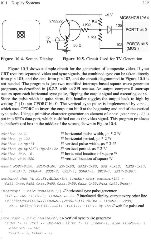
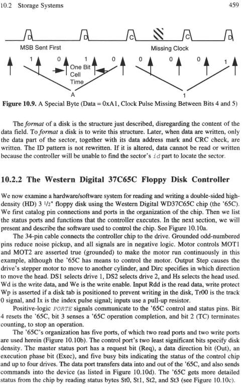
Figure 10.3. The Composite Video Signal
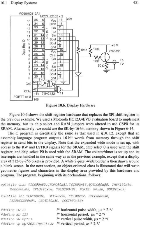
10.1.2 A 6812 SPI Display
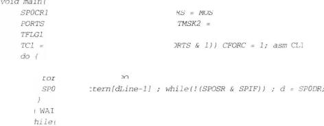
We are fortunate that the 6812 has a built-in counter and shift register able to generate the synchronization pulses and the bit stream to implement a primitive CRT display. The 6812 output compare timers, described in Chapter 7, are capable of generating the vertical and horizontal sync pulses; and the serial peripheral interface (SPI), introduced in Chapter 4, has the capability of generating a CRT display having poor, but useful, resolution. The upcoming C procedure main() should produce a picture as shown in Figure 10.4, using the simple hardware diagrammed in Figure 10.5 with a single-chip 6812. It is quite useful for explaining the principles of CRT display systems, since it uses familiar 6812 peripherals. It might be useful for multicomputer systems as a diagnostic display available on each microcomputer. We have found it helpful in testing some bargain-priced CRTs when we did not have specifications on the permissible range of horizontal and vertical sync pulse widths and frequencies. This little program lets us easily test these systems to generate the specifications. We now describe how that builtin CRT generator in the 6812 can produce a CRT display.
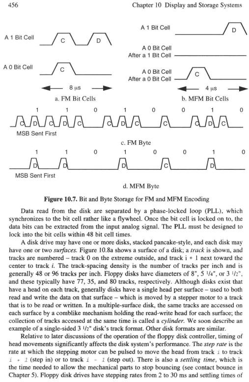
A combined sync signal is generated that is the exclusive-OR of the vertical and horizontal sync signals. The CRT's sync separator outputs its high-frequency component to the horizontal oscillator and a low-frequency component to the vertical oscillator. By inverting the horizontal sync signal during vertical retrace, the signal's low-frequency component has a pulse during this period. The high-frequency output of the sync separator continues to synchronize the horizontal oscillator during vertical retrace, while the low-frequency component synchronizes the vertical oscillator during vertical retrace.


474 |
Chapter 10 Display and Storage Systems |
This text has been fun for us. Microcomputers like the 6812 are such powerful tools that it challenges the mind to dream up ways to use them well. We sincerely hope you have enjoyed reading about and experimenting with the 6812microcomputer.
Do You Know These Terms?
See page 36for instructions.
National |
Bresenham |
logical sector |
specify |
Television |
algorithm |
number (LSN) |
read id |
System |
window |
interleave factor |
sense drive |
Committee |
clipped |
unformatted |
sense status |
(NTSC) |
secondary storage |
capacity |
command phase |
raster line |
surface |
formatted capacity |
execution phase |
frame |
track |
format |
result phase |
pixel |
cylinder |
seek |
verify |
NTSC composite |
step rate |
read sector |
boot sector |
video signal |
settling time |
implied seek |
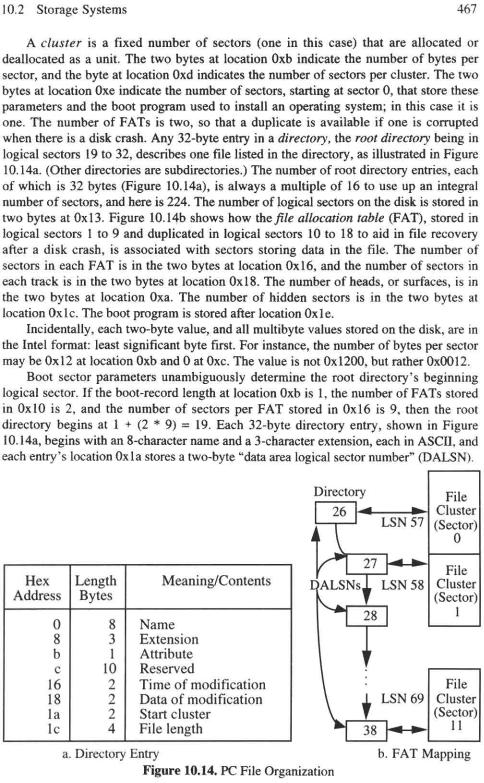
cluster |
horizontal retrace |
fill |
write sector |
directory |
vertical retrace |
sector |
restoring |
root directory |
horizontal sync |
index hole |
recalibrating the |
file allocation |
vertical sync |
index pulse |
drive |
table (FAT) |
sync separator |
|
|
|


Problems |
479 |
a. Write a function member char get () for class file that will output the next byte of the file (at location posi tiers), but if this requires reading in another sector, the sector previously stored in the buffer is written back.
b. Write a function member put (char c) for class file that will write c into the next byte of the file (at location posi tiori), but if this requires writing into another sector, that sector is read into the buffer.
c. Explain why an object of class file should be declared or blessed with "permissions" read-only, write-only, or update to make the file both readable and writeable at the same time. In particular, comment on how long reading or writing can take, in the worst case, for each example. How can our class f i 1 e be modified to permit this capability to be declared in the constructor and used in the function members?

Appendix
Using the HIWARE CD-ROM
This appendix helps you use the accompanying CD-ROM to simulate your programs, and to download and debug them on EVB Boards and other target microcontrollers.
A-l Loading HIWARE Software
Open the CD ROM, check "installation", and choose the Motorola HC12 target. If you have 60 Megabytes of disk space, load all parts of the tool chain.
A-2 Running the Simulator
You can use the software on the CD-ROM to simulate your programs on a PC running Windows 95 or later, or Windows NT 5.0 or later, without using any extra hardware. Using Acrobat Reader 3.0 or later, run the \hiware\docu\hcl2\demol2.pdf file. This file provides a tutorial guide on how to load and run the compiler, linker, and simulator. Following this guide, compile, link, and simulate the program Fibo.c.
A very simple way to experiment with other programs is to modify the file Fibo.c. Using any text editor, such as NOTEPAD, rewrite the Fib.c file with a program that you wish to study. Compile, link, and simulate the modified program Fib.c. You can rewrite Fibo.c each time you wish to study a new program. You can use more sophisticated echniques, but this simple technique can get you started with minimal effort.
A-3 Running Examples from This Book
Note that the folder EXAMPLES on the CD-ROM has files in it such as Ei2.txt. These files contain examples from this text book, which you can copy-and-paste into Fibo.c, so that you can run these examples on the Hiwave simulator. The file Ei2.txt contains all the examples in Chapter 2 of this textbook, and the file Ei4.txt contains all he examples in Chapter 4 of this textbook, and so on. Copy this folder into your hard disk; most conveniently, put it into your HIWARE folder.
A-4 Downloading to a 'B32 Board
You can use the HIWARE software to download and debug Fibo.c. on the Motorola M68HC12B32EVB board (abbreviated the 'B32 board) as your target. Begin by simulating Fibo.c. on the Hiwave simulator, as described above. After you are comfortable with the simulator's operation, follow the procedures described in the hiware\docu\hcl2\manual\MWb2.pdffile. You should always apply the 5V power after ail connections are made, and you should never change a connector while power is applied to the 'B32 board.
481
482 Appendix 1 Using the HIWARE CD-ROM
A-5 POD-Mode BDM Interface
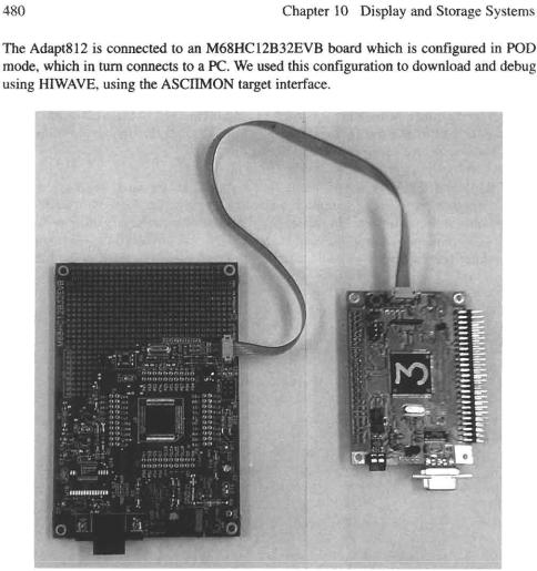
You can run HIWARE on a PC running Windows 95 or later, or Windows NT 5.0 or later, using the Motorola M68HC12B32EVB board in its POD mode, to connect a different target, such as an Technological Arts Adapt-812 board, or an Axiom PB68HC12A4 board, (called the target) to run experiments.
This technique utilizes the state-of-the-art background debug module BDM in your target, providing a debugger that runs in the M68HC12B32EVB board (called the POD) that is isolated from the target. If the target is not fully functional, the POD still functions and can help you debug the target. This technique also provides additional functionality to Hiwave, such as the ability to profile and analyze coverage. However, since more things can go wrong with a PC, a POD, and a target, than with just a PC, or a PC and a target M68HC12B32EVB, we recommend using this technique after you have had experience with the two simpler techniques described above.
Begin by runnin Fibo.c. on the Hiwave simulator, and then running Fibo.c. on the 'B32 board, as described above. After you are comfortable with the simulator's and 'B32 board's operation, reconnect the W3 to its 0 position and W4 to its 1 position to configure the board for POD mode, and reset the POD. Select the Asciimon target. Load Fibo.abs. You should be able to dupliciate what you did in the simulator and 'B32 board, running it on the Adapt-812 or PB68HC12A4 board.
You can use the Motorola SPI module, a more powerful BDI debugger, in place of the POD. Other similar BDI interface modules, but not all, are also compatible with Hiwave. Other target microcontrollers can be run using the POD or similar board.
A-5 Techniques for HIWARE Tools
We have had some experiences with HIWARE tools, which might help you use them more efficiently. We add a note here on our suggestions, to help you with this powerful software.
A problem with the current version is that when you change project files, the compiler/Iinker/hiwave debugger may read or write the wrong files, or fail to find the files it needs. We found that by shutting down all HIWARE programs, and starting them up again, the problem goes away. But you do not have to restart the computer. If you have verified that the paths to the files are correct, but you are unable to access them through the compiler/Iinker/hiwave debugger, then try restarting all HIWARE programs "from scratch". The same remedy is suggested when the Hiwave simulator or debugger fails to execute single-step commands, or breakpoints, correctly.
When dealing with different environments such as your own PC running Windows 95, workstations running Windows NT, and a PC running Windows 98 in the laboratory, keep separate complete project folders for each environment, and copy the source code from one to another folder. That way, you will spend less time readjusting the paths to your programs and HIWARE's applications when you switch platforms.
We hope that the CD-ROM supplied through HIWARE makes your reading of this book much more profitable and enjoyable. We have found it to be most helpful in debugging our examples and problem solutions.


486
indirect address 15 indirect I/O 162 indirect memory 262 induction motor 309 information frame 429 information hiding 80 information structure 55 inheritance 77 initialization ritual 141 initialize 30
initiator 435 input capture 382
input instruction 122 input port 95, 122 input state 150 input/output 3
integral cycle control 316 interleave factor 457 internal address 284 interpreter 149
interrupt 210 interrupt handler 27 interrupt inhibit bit 18 interrupt mask bit 18
interrupt service routine 27 inverting amplifier 317 isolated I/O 122
jump 6
jump to subroutine 15, 26
large-scale integrated circuit latch 101
latency time 27
lazy buffer management 260 LCD 311
LED 311
levels of abstraction 398 light-emitting diode 311 linear mode 317
linear variable displacement transformer 311 linear-select keyboard 233
link control 399 link variable 95 linked list 58
linked-list structure 152 liquid crystal display 311 list 58
loadS
load cell 314 local data 15
location counter 28
Index
lock 123
logic diagram 96 logic instruction 21 logic timer 148 logical operator 50
logical sector number 457 low 94
low storbe 106 low-pass filter 327 low-power Schottky 96
machine code 4 machine state 27 macro 8, 70 Manchester code 400
mask microprocessor 211, 212 master/slave 401
matrix keyboard 234
Mealy sequential machine 150 medium 399
medium-scale integrated circuit 96 memorize 5
memorize cycle 7 memory access time 102 memory clock 7
memory cycle 7, 102, 106 memory cycle time 102 memory map 35
memory variable 95 memory-mapped I/O 23, 122 message level 400 microcomputer 9 microcontroller 9 microinstruction 7 microprocessor 9 microprogramming 7 mnemonic 4
modem 405 module 95 monitor 27 motor 309
move instruction 17 multi-input-multi-output controller 352 multiplying D-to-A converter 335 multithread scheduling 245
n-rekey rollover 248 narrow mode 106
National Television System Committee 446 negate a variable 94
negative bit 18 negative logic 95


LIMITED WARRANTY AND DISCLAIMER OF LIABILITY
ACADEMIC PRESS ("AP") AND ANYONE ELSE WHO HAS BEEN INVOLVED IN THE CREATION OR PRODUCTION OF THE ACCOMPANYING CODE ("THE PRODUCT") CANNOT AND DO NOT WARRANTTHE PERFORMANCE OR RESULTS THAT MAY BE OBTAINED BY USING THE PRODUCT. THE PRODUCT IS SOLD "AS IS" WITHOUT WARRANTY OF ANY KIND (EXCEPT AS HEREAFTER DESCRIBED), EITHER EXPRESSED OR IMPLIED, INCLUDING, BUT NOT LIMITED TO, ANY WARRANTYOF PERFORMANCE OR ANY IMPLIED WARRANTYOF MERCHANTABILITY OR FITNESS FOR ANY PARTICULAR PURPOSE. AP WARRANTS ONLY THAT THE OPTICAL DISK(S) ON WHICH THE CODE IS RECORDED IS FREE FROM DEFECTS IN MATERIAL AND FAULTY WORKMANSHIP UNDER THE NORMAL USE AND SERVICE FOR A PERIOD OF NINETY (90) DAYS FROM THE DATE THE PRODUCT IS DELIVERED. THE PURCHASER'S SOLE AND EXCLUSIVE REMEDY IN THE EVENT OF A DEFECT IS EXPRESSLY LIMITED TO EITHER REPLACEMENT OF THE DISK(S) OR REFUND OF THEPUR– CHASE PRICE, ATAP'S SOLE DISCRETION.
IN NO EVENT, WHETHER AS A RESULT OF BREACH OF CONTRACT, WARRANTYOR TORT (INCLUDING NEGLIGENCE), WILL AP OR ANYONE WHO HAS BEEN INVOLVED IN THE CREATION OR PRODUCTION OF THE PRODUCT BE LIABLE TO PURCHASER FOR ANY DAMAGES, INCLUDING ANY LOST PROFITS, LOST SAVINGS OR OTHER INCIDENTAL OR CONSEQUENTIAL DAMAGES ARISING OUT OF THE USE OR INABILITY TO USE THE PRODUCT OR ANY MODIFICATIONS THEREOF, OR DUE TO THE CONTENTS OF THE CODE, EVEN IF AP HAS BEEN ADVISED OF THE POSSIBILITY OF SUCH DAMAGES, OR FOR ANY CLAIM BY ANY OTHER PARTY.
ANY REQUEST FOR REPLACEMENT OF A DEFECTIVE DISK MUST BE POSTAGE PREPAID AND MUST BE ACCOMPANIED BY THE ORIGINAL DEFECTIVE DISK, YOUR MAILING ADDRESS AND TELEPHONE NUMBER, AND PROOF OF DATE OF PURCHASE AND PURCHASE PRICE. SEND SUCH REQUESTS, STATING THE NATURE OF THE PROBLEM, TO ACADEMIC PRESS CUSTOMER SERVICE, 6277 SEA HARBOR DRIVE, ORLANDO, FL 32887, 1-800-321-5068. AP SHALL HAVE NO OBLIGATION TO REFUND THE PURCHASE PRICE OR TO REPLACE A DISK BASED ON CLAIMS OF DEFECTS IN THE NATURE OR OPERATION OF THE PRODUCT.
SOME STATES DO NOT ALLOW LIMITATION ON HOW LONG AN IMPLIED WARRANTY LASTS, NOR EXCLUSIONS OR LIMITATIONS OF INCIDENTAL OR CONSEQUENTIAL DAMAGE, SO THE ABOVE LIMITATIONS AND EXCLUSIONS MAY NOT APPLY TO YOU. THIS WARRANTYGIVES YOU SPECIFIC LEGAL RIGHTS, AND YOU MAY ALSO HAVE OTHER RIGHTS WHICH VARY FROM JURISDICTION TO JURISDICTION.
THE RE-EXPORT OF UNITED STATES ORIGIN SOFTWARE IS SUBJECT TO THE UNITED STATES LAWS UNDER THE EXPORT ADMINISTRATION ACT OF 1969 AS AMENDED. ANY FURTHER SALE OF THE PRODUCT SHALL BE IN COMPLIANCE WITH THE UNITED STATES DEPARTMENT OF COMMERCE ADMINISTRATION REGULATIONS. COMPLIANCE WITH SUCH REGULATIONS IS YOUR RESPONSIBILITY AND NOT THE RESPONSIBILITY OFAP.