

Chapter 6 - Samples
Previous page |
Table of contents |
Chapter overview |
Next page |
Shift registers
There are two types of shift registers: input and output. Input shift registers receive data in parallel, through 8 lines and then send it serially through two lines to a microcontroller. Output shift registers work in the opposite direction; they receive serial data and on a "latch" line signal, they turn it into parallel data. Shift registers are generally used to expand the number of input-output lines of a microcontroller. They are not so much in use any more though, because most modern microcontrollers have a large number of input/output lines. However, their use with microcontrollers such as PIC16F84 is very important.
Input shift register 74HC597
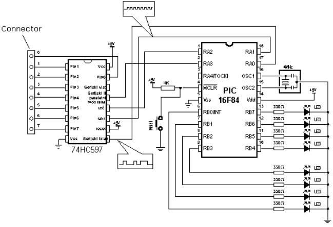
Input shift registers transform parallel data into serial data and transfer it to a microcontroller. Their working is quite simple. There are four lines for the transfer of data: clock, latch, load and data. Data is first read from the input pins by an internal register through a 'latch' signal. Then, with a 'load' signal, data is transferred from the input latch register to the shift register, and from there it is serially transferred to a microcontroller via 'data' and 'clock' lines.
An outline of the connection of the shift register 74HC597 to a micro, is shown below.
http://www.mikroelektronika.co.yu/english/product/books/PICbook/6_08Poglavlje.htm (1 of 7) [4/2/2003 16:19:01]
Chapter 6 - Samples
How to connect an input shift register to a microcontroller
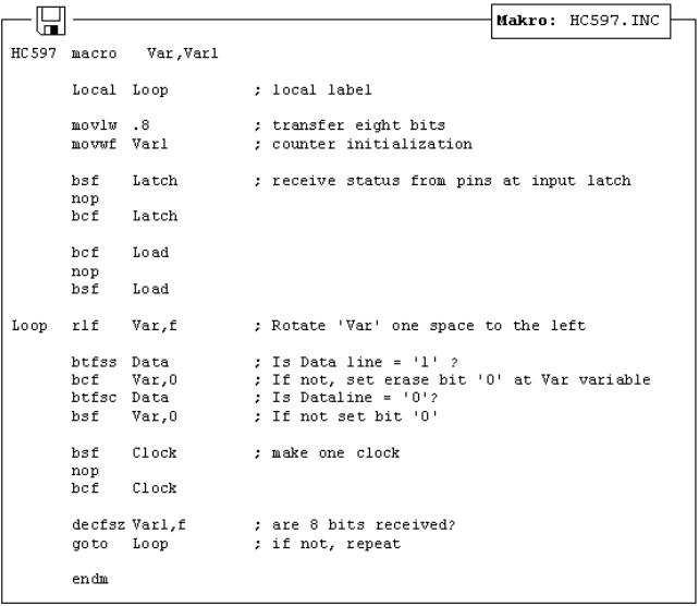
In order to simplify the main program, a macro can be used for the input shift register. Macro HC597 has two arguments:
HC597 macro Var, Var1
Var variable where data from shift register input pins is transferred
Var1 loop counter
Example: HC597 data, counter
Data from the input pins of the shift register is stored in data variable. Timer/counter variable is used as a loop counter.
Macro listing:
http://www.mikroelektronika.co.yu/english/product/books/PICbook/6_08Poglavlje.htm (2 of 7) [4/2/2003 16:19:01]
Chapter 6 - Samples
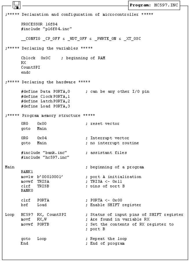
Example of how to use the HC597 macro is given in the following program. Program receives data from a parallel input of the shift register and moves it serially into the RX variable of the microcontroller. LEDs connected to port B will indicate the result of the data input.
http://www.mikroelektronika.co.yu/english/product/books/PICbook/6_08Poglavlje.htm (3 of 7) [4/2/2003 16:19:01]
Chapter 6 - Samples
Output shift register
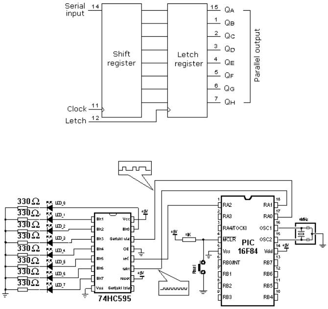
Output shift registers transform serial data into parallel data. On every rising edge of the clock, the shift register reads the value from data line, stores it in temporary register, and then repeats this cycle 8 times. On a signal from 'latch' line, data is copied from the shift register to input
http://www.mikroelektronika.co.yu/english/product/books/PICbook/6_08Poglavlje.htm (4 of 7) [4/2/2003 16:19:01]
Chapter 6 - Samples
register, thus data is transformed from serial into parallel data.
An outline of the 74HC595 shift register connections is shown on the diagram below:
Connecting an output shift register to a microcontroller
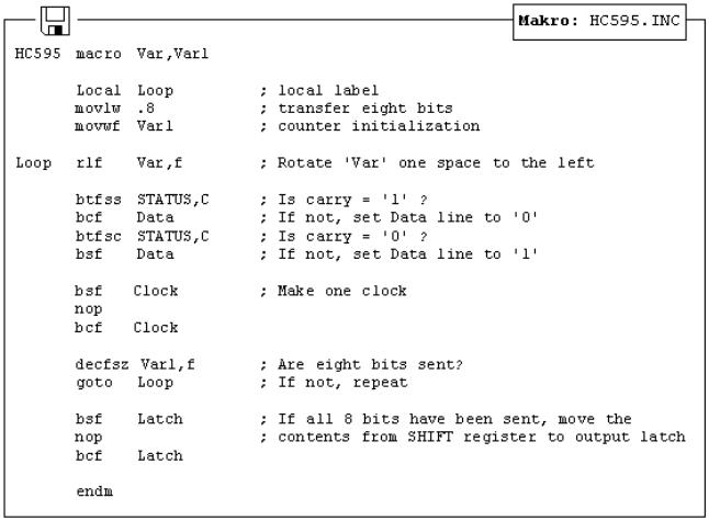
Macro used in this example is found in hc595.inc file, and is called HC595. Macro HC595 has two arguments:
HC595 macro Var, Var1
Var variable whose contents is transferred to outputs of shift register.
Var1 loop counter
Example: HC595 Data, counter
The data we want to transfer is stored in data variable, and counter variable is used as a loop counter.
http://www.mikroelektronika.co.yu/english/product/books/PICbook/6_08Poglavlje.htm (5 of 7) [4/2/2003 16:19:01]
Chapter 6 - Samples
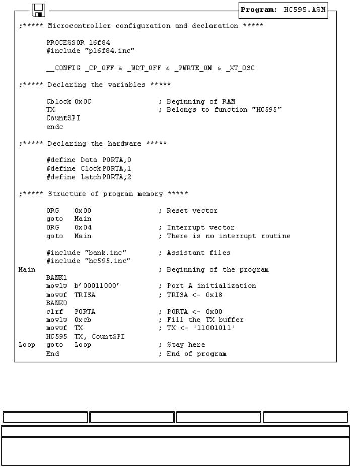
An example of how to use the HC595 macro is given in the following program. Data from variable TX is serially transferred to shift register. LEDs connected to the parallel output of the shift register will indicate the state of the lines. In this example value 0xCB (1100 1011) is sent so that the eighth, seventh, fourth, second and first LEDs are illuminated.
http://www.mikroelektronika.co.yu/english/product/books/PICbook/6_08Poglavlje.htm (6 of 7) [4/2/2003 16:19:01]
Chapter 6 - Samples
Previous page |
Table of contents |
Chapter overview |
Next page |
© Copyright 1999. mikroElektronika. All Rights Reserved. For any comments contact webmaster.
http://www.mikroelektronika.co.yu/english/product/books/PICbook/6_08Poglavlje.htm (7 of 7) [4/2/2003 16:19:01]