

The insider's guide to the Philips ARM7-based microcontrollers (T. Martin, 2005)
.pdfIntroduction to the LPC2000 |
4 – User Peripherals |
|
|
Bit Timing
Unlike many other serial protocols, the CAN bit rate is not just defined by a baud rate prescaler. The CAN peripheral contains a Baud rate prescaler but it is used to generate a time quanta i.e. a time slice. A number of these time quanta are added together to get the overall bit timing.
CAN bit timing:
Unlike other serial protocols the CAN bit period is constructed as a number of segments that allow you to tune the CAN data transmission to the channel being used.
The bit period is split into three segments. First is the sync segment, which is fixed at one time quanta long. The next two segments are Tseg1 and Tseg2 where the user defines the number of time quanta in each region. The minimum number of time quanta in a bit period is 8 and the maximum is 25. The receiving sample point is at the end of Tseg1 so changing the ratio of Tseg1 to Tseg2 adjusts the sample point. This allows the CAN protocol to be tuned to the transmission channel. If you are using long transmission lines, the sample point can be moved backwards. If you have drifting oscillators you can bring the sample point forward. In addition, the receivers can adjust their bit rate to lock onto the transmitter. This allows the receivers to compensate for small variations in the transmitter bit rate. The amount that each bit can be adjusted is called the “synchronous jump width” and may be set to between 1 – 4 time quanta and is again user definable.
To calculate the bit timing, the formula is given by
Bit rate = Pclk/(BRP x ( 1 + Tseg1 + Tseg2))
Where: BRP = Baud rate prescaler
This calculation has a lot of unknowns. If we assume that we want to reach a bit rate of 125K with a 60 MHz Pclk and a sample point of about 70%, here is how the BRP calculation is performed.
The total number of time quanta in a bit period is given by (1+Tseg1+Tseg2) . If we call this term QUANTA and rearrange the equation in terms of the baud rate prescaler:
BRP = |
Pclk/(Bit rate x QUANTA) |
110
Introduction to the LPC2000 |
4 – User Peripherals |
|
|
Using our known values:
BRP = |
60 MHz/(125K x QUANTA) |
Now we know that we can have between 8 and 25 time quanta in the bit period, so using a spreadsheet we can substitute in integer values between 8 and 25 for QUANTA until we get an integer value for BRP.
In this case when QUANTA = 16 BRP = 30;
Then 16 = Quanta = ( 1+Tseg1+Tseg2)
So we can adjust the ratio between Tseg1 and Tseg2 to give us the desired sample point.
Sample point = |
(QUANTA x 70)/100 |
Hence 16 *0.7 = 11.2. This gives Tseg 1 = 10, Tseg2 = 5 and the sample point = 68.8%
The value for the synchronous jump width may be calculated via the following rule of thumb.
Tseg2 >= 5 Tq then program SJW to 4
Tseg2 < 5 Tq then program SJW to (Tseg2 - 1) Tq
In this case SJW = 4.
111

Introduction to the LPC2000 |
4 – User Peripherals |
|
|
CAN Message Transmission
In the LPC2000, each CAN controller has a number of status and control registers plus three transmit buffers and a receive buffer.
In order to configure CAN controller we must program the bit timing register. However the bit timing register is a protected register and may only be written to when the CAN controller is in reset. Bit zero of the mode register is used to place the CAN controller into reset.
The CAN bit timing is defined by 5 separate parameters
We can use the values calculated above to initialise one of the CAN controllers to 125Kbit/sec. It is important to note that the values stored in the register are the calculated values minus 1. This ensures that no timing segment is set to zero. Once the CAN controller has been initialised, it is possible to transmit a message by writing to a transmit buffer. Each transmit buffer is made up of four words.
112

Introduction to the LPC2000 |
4 – User Peripherals |
|
|
Two words are used to hold the 8 bytes of data and one word holds the message identifier. The final register is the frame information register.
The parameters of each CAN message are defined in each message buffer
This register holds the values of the DLC and the RTR bit. In addition, there is a frame format (FF) bit that defines whether the message has an 11-bit or 29-bit identifier. As there are three TX buffers it is possible to define an internal priority for each TX buffer. If several buffers are scheduled simultaneously, the CAN controller will use internal arbitration to decide which is transmitted first. This can be done in one of two ways; if the TPM bit in the MODE register is Zero, the transmit buffer with the lowest value identifier will be sent first. If TPM is high, then arbitration will use the values stored in the PRIO field in the Tx Frame Information register and the buffer with the lowest PRIO value is sent first. Once the buffer has been filled with a message, transmission can be started by setting the Transmit request bit (TR) in the COMMAND register. The code below shows some code fragments to initialise the CAN peripheral and transmit a message.
C2MOD = 0x00000001; C2BTR = 0x001C001D; C2MOD = 0x00000000;
//Set CAN controller into reset //Set bit timing to 125k //Release CAN controller
if(C2SR & 0x00000004) |
//See if Tx Buffer 1 is free |
||
{ |
|
|
//Set DLC to 4 bytes |
C2TFI1 = 0x00040000; |
|
||
C2TID1 = |
0x00000022; |
|
//Set address to 0x22 Standard Frame |
C2TDA1 = |
NetworkData; |
//Copy some data into first four bytes |
|
C2CMR = |
0x00000001; |
|
//Transmit the message |
} |
|
|
|
113
Introduction to the LPC2000 |
4 – User Peripherals |
|
|
Exercise 25: CAN Transmit
This exercise configures the second CAN channel for 125K bits\second and repeatedly transmits a CAN message frame.
114

Introduction to the LPC2000 |
4 – User Peripherals |
|
|
CAN Error Containment
The CAN protocol has five methods of error containment built into the silicon. If any error is detected, it will cause the transmitter to resend the message so the CPU does not need to intervene unless there is a gross error on the bus. There are three error detection methods at the packet level; form check, CRC, and acknowledge plus two at the bit level; bit check error and bit stuffing error. Within the CAN message there are a number of fields that are added to the basic message. On reception, the message telegram is checked to see if all these fields are present. If not, the message is rejected and an error frame is generated. This ensures that a full, correctly formatted message has been received.
Frame Check:
The frame check tests that a correctly formatted CAN message has been received.
Each message must be acknowledged by having a dominant bit inserted in the acknowledge field. If no acknowledge is received, the transmitter will continue to send the message until an acknowledge is received.
Acknowledge:
All CAN frames must be acknowledged. If there is no handshake, the message will be re-sent
The CAN message packet also contains a 15 bit CRC which is automatically generated by the transmitter and checked by the receiver. This CRC can detect and correct 4 bits of error
115

Introduction to the LPC2000 |
4 – User Peripherals |
|
|
in the region from the start-of-frame to the beginning of the CRC field. If the CRC fails and the message is rejected, an error frame is placed onto the bus.
CRC: A 15 bit CRC is automatically generated which is a weighted polynomial checksum that provides error detection and correction across the message packet
Once a node has won arbitration it will start to write its message onto the bus. As during arbitration as each bit is written onto the bus, the CAN controller is reading back the level written onto the bus. As the node has won arbitration nothing else should be transmitting so each bit level written onto the bus must match the level read back. If the wrong level is read back, the transmitter generates an error frame and reschedules the message. The message is sent in the next message slot but must still go through the arbitration process with any other scheduled message.
Bit check error:
Once the arbitration has finished the write and read back mechanism is use for bitwise error checking
This leads to one of the golden rules in developing a CAN network. In a CAN network, every identifier must be uniquely generated. So you must not have the same identifier sent from two different nodes. If this happens, it is possible that two messages with the same ID are scheduled together, both messages will fight for arbitration and both will win as they have the same ID. Once they have won arbitration they will both start to write their data onto the bus. At some point this data will be different and this will cause a bit check error. Both messages will be rescheduled, win arbitration and go into error again. Potentially this ‘deadly embrace’ can lock up the network, so beware!
116

Introduction to the LPC2000 |
4 – User Peripherals |
|
|
At the bit level, CAN also implements a bit stuffing scheme. For every five dominant bits in a row, a recessive bit is inserted.
Bit Stuffing:
For every five bits of one logic in a row a stuff bit of the opposite logic is inserted. The error frame breaks this rule by being six dominant bits in a row
This helps to break up DC levels on the bus and provides plenty of edges in the bit stream which are used for resynchronisation. An error frame in the CAN protocol is simply six dominant bits in a row. This allows any CAN controller to assert an error onto the bus as soon as the error is detected, without having to wait until the end of a message. Internally each CAN controller has two counters.
Error counters:
The CAN controller moves between a number of error states that allow a node to fail in an elegant fashion, without blocking the bus
These are a receive error counter and a transmit error counter. These counters will count up when receiving or transmitting an error frame. If either counter reaches 128, then the CAN controller will enter an ‘error passive’ mode. In this mode it still responds to error frames but if it generates an error frame, it writes recessive bits in place of dominant bits. If the transmit error counter reaches 255 then the CAN controller will go into a bus-off condition and take no further part in CAN communication. To restart communication, the CPU must intervene to reinitialise the controller and put it back onto the bus. Both these mechanisms are to ensure that if a node goes faulty, it will fail gracefully and not block the bus by continually generating error frames.
The LPC2000 CAN controllers have a number of error detection mechanisms. First of all, the current count of the transmit and receive error counters can be read in the Global Status Register.
Also in this register are two error flags, the Bus Status flag will be set when the maximum error count is reached and the CAN controller is removed from the bus. The second error flag is the Error Status flag, which is set when the CAN error counters reach a warning limit. This warning limit is an arbitrary value that is set by writing a value into the Error Warning limit register. The default value in this register is 96. Like the bit timing registers, the EWL
117
Introduction to the LPC2000 |
4 – User Peripherals |
|
|
register may only be modified when the CAN controller is in reset. In addition, the Interrupt Capture Register provides extensive diagnostics for managing events on the CAN bus.
The CAN controller has the following interrupt sources,
1.Transmit interrupt (one for each buffer)
2.Receive interrupt
3.Error Warning
4.Data overrun
5.Wake up
6.Error Passive
7.Arbitration lost
8.Bus error
9.ID ready
CAN Message Reception
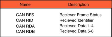
Once initialised, the CAN controller is able to receive messages into its receive buffer. This is similar in layout to the transmit buffers
The Rx Frame Status register is analogous to the Tx Frame information register. However it has two additional values. These are the ID Index and the BP bit and these will be explained in the next section.
The code below demonstrates how to receive a CAN message:
int main(void) |
|
|
{ |
|
//Set PClk to 60MHz |
VPBDIV = 0x00000001; |
||
IODIR1 = 0x00FF0000; |
// set all ports to output |
|
PINSEL1|= 0x00040000; |
//Enable Pin 0.25 as CAN1 RX |
|
C1MOD = 0x00000001; |
//Set CAN controller into reset |
|
C1BTR = 0x001C001D; |
//Set bit timing to 125k |
|
C1IER =0x00000001; |
//Enable the Receive interrupt |
|
VICVectCntl0 = 0x0000003A; |
//select a priority slot for a given interrupt |
|
VICVectAddr0 |
= (unsigned)CAN1IRQ; //pass the address of the IRQ |
|
VICIntEnable |
= 0x04000000; |
//into the VIC slot |
//enable interrupt |
||
AFMR = 0x00000001; |
//Disable the Acceptance filters |
|
C1MOD = 0x00000000; |
//Release CAN controller |
|
while(1){;}
}
118
Introduction to the LPC2000 |
4 – User Peripherals |
|
|
void CAN1IRQ (void) __irq |
|
||
{ |
~C1RDA; |
//clear output |
pins |
IOCLR1 = |
|||
IOSET1 = |
C1RDA; |
//set output pins |
|
C1CMR = |
0x00000004; |
//release the |
receive buffer |
VICVectAddr = 0x00000000; //Signal |
the end of interrupt |
||
} |
|
|
|
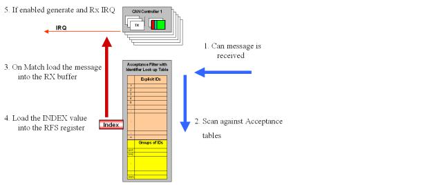
Acceptance Filtering
While the receive example shown above will work perfectly well, it suffers from two problems. Firstly, it receives every message transmitted on the bus. In a fully loaded CAN bus this could mean a message would be received every 72us. As the LPC2000 has up to 4 CAN controllers, the CPU would have to spend a lot of time just managing the CAN busses. Secondly, once the message has been received the CAN controller would have to read and decode the message identifier in order to decide what to do with the message. In order to overcome these problems, the LPC2000 CAN controllers have a sophisticated acceptance filtering scheme. The acceptance filter is used to screen messages as they come in from the CAN bus. The acceptance filter can be programmed to pass or block message identifiers before they enter the CAN controller for processing. This prevents unwanted messages entering the CAN receive buffer and consequently greatly reduces the overhead on the CPU. The acceptance filter has 2K of RAM (512 x 32), which may be allocated into tables of identifiers. This allows ranges of messages and individual messages to be able to enter into the CAN receive buffer.
Acceptance filters:
The CAN modules one 2K block of RAM which is used to set up filter tables to efficiently handle high bus loadings without overloading the CPU
As a message passes through the acceptance filter, it is assigned an ID Index. This is an integer number that relates to the message ID’s offset in the acceptance filter table. This number is stored in the RX Frame Status register. So rather than decode the raw message ID, it is easier and faster to use the index value to decide what message has been received.
119