

The insider's guide to the Philips ARM7-based microcontrollers (T. Martin, 2005)
.pdfIntroduction to the LPC2000 |
4 – User Peripherals |
|
|
Full CAN mode:
In full can mode the CAN RAM may also be configured as additional receive buffers which store incoming data for the CPU to read as required
The acceptance filter also has a full CAN mode. In this mode the messages are received and scanned against the table of permissible identifiers. If a match is made, the message is stored not in the CAN controller receive buffer but in a dedicated message buffer within the acceptance filter memory. In this mode, each message has its own unique message buffer at a fixed location, making all the CAN data easily accessible from the CPU.
Configuring The Acceptance Filter
The acceptance filter is configured by seven registers. Control of the filter is via the mode register. The various ID tables are configured by the next five registers and the seventh register is an error reporting register.
Before configuration of the acceptance filter can start it must be disabled. This is done by setting the AccOff bit and clearing the AccBP bit in the acceptance filter mode register. If the CAN controller is run with this configuration, then all messages on the bus will be received.
The Acceptance filter mode register provides global control of the acceptance filter
120
Introduction to the LPC2000 |
4 – User Peripherals |
|
|
Once the acceptance filter is disabled, each of the four filter tables may be configured. The four tables are as follows:
Individual standard identifiers |
(11 bit ID) |
Groups of standard identifiers |
(11 bit ID) |
Individual Extended identifiers |
(29 bit ID) |
Groups of extended identifiers |
(29 bit ID) |
The acceptance filter RAM starts at 0xE0038000. Each of the tables must be defined and fixed at absolute locations in the filter RAM. The start address of each table should then be written into the relevant acceptance filter register. The tables should start at the beginning of RAM and use the memory contiguously. Finally, the address of the last used location of RAM should be written into the End of Table register. To enable the Acceptance filter, set the ACCoff bit to logic one and AccBP bits to zero.
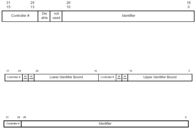
Each of the tables is constructed as follows;
The Individual Standard identifier table allows you to define individual 11-bit identifiers that will pass through the acceptance filter. Each definition takes two bytes, the first 11 bits contains the message identifier to be passed. This is followed by a bit to dynamically enable or disable this filter entry. Finally, the top three bits associates this filter entry with a particular CAN controller.
The group standard identifier table uses the same format but two entries are used to define the upper and lower identifier address range for messages that are allowed to pass through the acceptance filter
The individual extended identifier table uses four bytes per entry, as shown above. The first 29 bits define the message identifier to be passed through the acceptance filter and the top three bits associates the filter entry with a particular CAN controller. The group extended identifier table uses two words in the same format as the individual extended table to build up a start and end identifier values in the same fashion as the standard message group table
121

Introduction to the LPC2000 |
4 – User Peripherals |
|
|
The following code shows how the acceptance filters may be configured for the basic CAN mode.
unsigned |
int |
StandardFilter[2] |
_at_ 0xE0038000; |
//Declare the standard |
unsigned |
int |
GroupStdFilter[2] |
_at_ 0xE0038008; |
//acceptance filter table |
//Next the standard Group |
||||
//filter |
table |
|
|
|
unsigned |
int |
IndividualExtFilter[2] _at_ 0xE0038010; //Now the extended filter |
||
unsigned |
int |
|
|
//table |
GroupExtFilter[2] _at_ 0xE0038018; //Finally the Group extended |
||||
//filter table |
|
|
||
AFMR = 0x00000001; |
//Disable the Acceptance filters |
|||
StandardFilter[0] = 0x20012002; |
//Setup the standard filter table |
|||
StandardFilter[1] = 0x20032004; |
//Allow Ids 1,2,3 & 4 |
|||
SFF_sa = 0x00000000; |
//Set start address |
of Standard |
table |
SFF_GRP_sa = 0x00000008; |
//Set start address |
of Standard |
group table |
EFF_sa = 0x00000008; |
//Set start address |
of Extended |
table |
EFF_GRP_sa = 0x00000008; |
//Set start address |
of Extended |
group table |
ENDofTable = 0x00000008; |
//Set end of table address |
|
|
AFMR = 0x00000000; |
//Enable Acceptance filters |
|
|
C1MOD = 0x00000000; |
//Release CAN controller |
|
|
Exercise 26 CAN Receive
Like the last exercise this example configures the CAN peripheral for 125Kbits/sec and sets the acceptance filters to receive one of three message frames.
Summary
This chapter is a bit of a moving target! The LPC2000 is a rapidly growing family with new variants being released on a regular basis. Check the CD that came with this book for a .PDF update to this chapter or keep an eye on the web at http://www.hitex.co.uk/arm/lpcbook
If you have worked through this and the proceeding chapters, you should now have a firm grasp of the LPC2000 family the ARM7 CPU and the necessary development tools. Appendix B lists further reading and web resources for the ARM7 and the LPC2000 in particular.
122
Introduction to the LPC2000 |
4 – User Peripherals |
|
|
123
Introduction to the LPC2000 |
5 – Tutorial With Keil Tools |
|
|
Chapter 5: Keil Tutorial
This chapter contains worksheets for the practical examples that are available on the CD. There are two sets of examples one for the Keil compiler and one for the GNU compiler. This chapter is written for the Keil compiler. If you want to use the GNU compiler you should start with Appendix A which details the non-ANSI additions to the GCC compiler. Appendix A also contains example worksheets for the first six exercises that deal with the specifically with GNU tools. After exercise six you can rejoin this chapter and use either the GNU or Keil examples for the remaining examples.
Installation
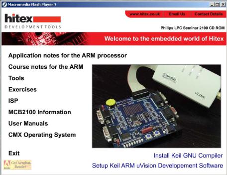
All the necessary software for the practical examples is on the CD that comes with this book. If you place the CD in the drive on your PC the following window will appear.
1.First it is necessary to install the Keil uVISION software, this will also install the Keil compiler.
2.If you wish to use the GNU compiler you will need to install this separately once uVISION is installed.
Next install the example set for the compiler you plan to use
Finally install the Philips ISP flash programming tool
Once the software has been installed you are ready to start the tutorial exercises
124
Introduction to the LPC2000 |
5 – Tutorial With Keil Tools |
|
|
Using the Keil UVISION IDE
This section will cover the development tools that can be used to develop code for the LPC2000. In this book all the example are written for the Keil ARM toolset. The Keil toolset comprises of the UVISION IDE which contains an editor and project manager, an ARM7 Compiler and linker and a Software simulator. The simulator will simulate the ARM7 core and the LPC2000 peripherals so it is possible to see the full operation of the chip by just using the simulator. An evaluation version of the toolset
is available free from the Keil website at www.keil.com or on the CD supplied with this book. It is also possible to purchase a starter kit which contains an evaluation board and JTAG debugger that allows you to develop code on a real target device.
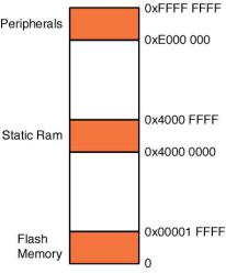
The Keil ARM compiler allows us to write in the C language and compile code to run on the LPC2000 devices. In order to cope with the microcontroller architecture the compiler has a number of non ANSI extensions that allow us to handle features such as interrupts ARM/Thumb interworking and accessing device peripherals. Before we start its worth looking at a simplified memory map of an LPC2000 so we can understand how to build a project.
The memory map of the LPC21xx is a linear 40 GB address space with regions for on chip flash, static ram and peripherals
Since the reset and exception vector table are located from zero upwards the on chip flash memory is located from zero for up to 256K. The on chip SRAM starts at 0x40000000 for up to 64K and the on chip peripherals are mapped from 0xE0000000 to the top of memory.
Before we begin to look at the compiler in detail I will run through a step by step tutorial on how to set up a UVISION project, compile the code and run the debugger. This does not cover all the features of uVISION but once you have a basic understanding of the IDE feel free to explore. If you copy the example from the CD onto you hard disk the source files referred to below can be found in C:\examples\ex1-first project. Ok lets build our first project.
125
Introduction to the LPC2000 |
5 – Tutorial With Keil Tools |
|
|
Exercise 1: Using the Keil Toolset
This example is based on the source code that can be found in
C:\Work\EX1 first program
In this first exercise we will spend some time defining a first project, building the code and downloading it into the simulator for debugging. We will then cover the basic debugging functions of the Keil simulator.
Double click on the Keil Uvision3 icon to start the IDE. 
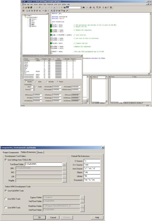
The Keil UVISION (a.k.a “uVISION”) IDE is designed to support several compilers, the Gnu C compiler, The ARM development suite and the Keil ARM compiler. Before compiling make sure you have the GNU compiler selected. This is done by activating the project workspace, right clicking and selecting manage components. In this dialog select the
Introduction to the LPC2000 |
5 – Tutorial With Keil Tools |
|
|
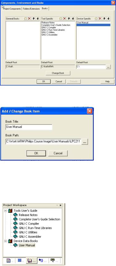
Folders/extensions tab and make sure the “Keil ARM tools” box is selected.
Next click on the “Books” tab.
Highlight the UserManual entry and press the “Change Book” button.
Now change the path to point to the LPC2000 user manual, which can be found on the CD in the “User Manuals” directory. You can now add any other documentation you wish through these menus.
Once the project has been fully configured the on-line documentation can be accessed through the Books tab in the project workspace window. The full Keil documentation for
127
Introduction to the LPC2000 |
5 – Tutorial With Keil Tools |
|
|
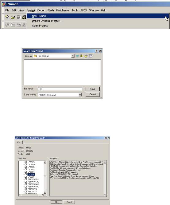
uVISION and the CARM compiler is found under “Complete Users Guide Selection” Once you have added the datasheet click the OK button to continue defining the project. From the menu bar select Project\new Project.
In the New project dialog navigate to your desired project directory.
In the new project dialog name the project “first.uv2” and select Save.
A ‘select new device for target’ dialog will appear. Navigate through the device database and select the Philips\LPC2129 folder and then OK.
128
Introduction to the LPC2000 |
5 – Tutorial With Keil Tools |
|
|
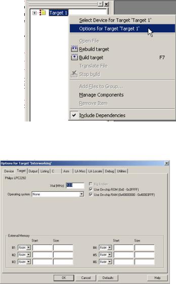
In the project browser highlight the ‘Target1’ root folder and select the local menu by pressing the right mouse button. In this menu select ‘options for target’.
In the ‘Target’ tab, set the simulation frequency to 12.000 MHz. Also make sure the “Use on chip Rom” and “Use On chip Ram” boxes are ticked.
In the LA Locate tab, make sure that the “Use memory layout from target dialog” box is ticked.
129