- •Table of Contents
- •Index
- •Keyword Reference
- •Installation
- •Installation of BASCOM
- •BASCOM IDE
- •Running BASCOM-AVR
- •File New
- •File Close
- •File Save
- •File Save As
- •File Print Preview
- •File Print
- •File Exit
- •View PinOut
- •View PDF viewer
- •View Error Panel
- •Edit Undo
- •Edit Redo
- •Edit Cut
- •Edit Copy
- •Edit Paste
- •Edit Find
- •Edit Find Next
- •Edit Replace
- •Edit Goto
- •Edit Toggle Bookmark
- •Edit Goto Bookmark
- •Edit Indent Block
- •Edit Unindent Block
- •Edit Remark Block
- •Program Compile
- •Program Syntax Check
- •Program Show Result
- •Program Simulate
- •Program Send to Chip
- •Tools Terminal Emulator
- •Tools LCD Designer
- •Tools LIB Manager
- •Tools Graphic Converter
- •Tools Stack Analyzer
- •Tools Plugin Manager
- •Tools Batch Compile
- •Options Compiler
- •Options Compiler Chip
- •Options Compiler Output
- •Options Compiler Communication
- •Options Compiler I2C, SPI, 1WIRE
- •Options Compiler LCD
- •Options Communication
- •Options Environment
- •Options Simulator
- •Options Programmer
- •Supported Programmers
- •ISP programmer
- •PG302 programmer
- •Sample Electronics cable programmer
- •KITSRUS Programmer
- •MCS Universal Interface Programmer
- •STK500 Programmer
- •Lawicel BootLoader
- •AVR ISP Programmer
- •USB-ISP Programmer
- •MCS Bootloader
- •Options Monitor
- •Options Printer
- •Window Cascade
- •Window Tile
- •Window Arrange Icons
- •Window Minimize All
- •Help About
- •Help Index
- •Help MCS Forum
- •Help MCS Shop
- •Help Support
- •Help Knowledge Base
- •Help Credits
- •BASCOM Editor Keys
- •Program Development Order
- •PlugIns
- •Font Editor
- •PinOut
- •BASCOM HARDWARE
- •Additional Hardware
- •AVR Internal Hardware
- •AVR Internal Registers
- •AVR Internal Hardware TIMER0
- •AVR Internal Hardware TIMER1
- •AVR Internal Hardware Watchdog timer
- •AVR Internal Hardware Port B
- •AVR Internal Hardware Port D
- •Adding XRAM
- •Attaching an LCD Display
- •Memory usage
- •Using the 1 WIRE protocol
- •Using the SPI protocol
- •Power Up
- •Chips
- •ATtiny22
- •ATtiny13
- •ATtiny15
- •ATtiny25
- •ATtiny45
- •ATtiny85
- •ATtiny26
- •ATtiny2313
- •ATMEGA8
- •ATMEGA16
- •ATMEGA32
- •ATMEGA48
- •ATMEGA88
- •ATMEGA168
- •ATMEGA64
- •ATMEGA103
- •ATMEGA128
- •ATMEGA161
- •ATMEGA162
- •ATMEGA163
- •ATMEGA165
- •ATMEGA169
- •ATMEGA323
- •ATMEGA603
- •ATMEGA8515
- •ATMEGA8535
- •BASCOM Language Fundamentals
- •Changes compared to BASCOM-8051
- •Language Fundamentals
- •Mixing ASM and BASIC
- •Assembler mnemonics
- •Reserved Words
- •Error Codes
- •Newbie problems
- •Tips and tricks
- •ASCII chart
- •BASCOM Language Reference
- •$BAUD
- •$BAUD1
- •$BOOT
- •$CRYSTAL
- •$DATA
- •$DEFAULT
- •$EEPLEAVE
- •$EEPROM
- •$EEPROMHEX
- •$EXTERNAL
- •$FRAMESIZE
- •$HWSTACK
- •$INCLUDE
- •$INITMICRO
- •$LCDPUTCTRL
- •$LCDPUTDATA
- •$LCDRS
- •$LCDVFO
- •$LOADER
- •$LOADERSIZE
- •$NOCOMP
- •$NOINIT
- •$NORAMCLEAR
- •$PROG
- •$PROGRAMMER
- •$REGFILE
- •$ROMSTART
- •$SERIALINPUT
- •$SERIALINPUT1
- •$SERIALINPUT2LCD
- •$SERIALOUTPUT
- •$SERIALOUTPUT1
- •$SWSTACK
- •$TIMEOUT
- •$TINY
- •$WAITSTATE
- •$XRAMSIZE
- •$XRAMSTART
- •1WIRECOUNT
- •1WRESET
- •1WREAD
- •1WSEARCHFIRST
- •1WSEARCHNEXT
- •1WVERIFY
- •1WWRITE
- •ACOS
- •ALIAS
- •ASIN
- •BASE64DEC
- •BASE64ENC
- •BAUD
- •BAUD1
- •BINVAL
- •BIN2GRAY
- •BITWAIT
- •BITS
- •BLOAD
- •BSAVE
- •BUFSPACE
- •BYVAL
- •CALL
- •CHECKSUM
- •CIRCLE
- •CLEAR
- •CLOCKDIVISION
- •CLOSE
- •CLOSESOCKET
- •CONFIG
- •CONFIG 1WIRE
- •CONFIG ACI
- •CONFIG ADC
- •CONFIG ATEMU
- •CONFIG BCCARD
- •CONFIG CLOCK
- •CONFIG CLOCKDIV
- •CONFIG COM1
- •CONFIG COM2
- •CONFIG COMx
- •CONFIG DATE
- •CONFIG DCF77
- •CONFIG DEBOUNCE
- •CONFIG I2CDELAY
- •CONFIG I2CSLAVE
- •CONFIG INPUT
- •CONFIG INTx
- •CONFIG GRAPHLCD
- •CONFIG KBD
- •CONFIG KEYBOARD
- •CONFIG LCD
- •CONFIG LCDBUS
- •CONFIG LCDMODE
- •CONFIG LCDPIN
- •CONFIG PORT
- •CONFIG PRINT
- •CONFIG PRINTBIN
- •CONFIG PS2EMU
- •CONFIG RC5
- •CONFIG SDA
- •CONFIG SCL
- •CONFIG SERIALIN
- •CONFIG SERIALIN1
- •CONFIG SERIALOUT
- •CONFIG SERIALOUT1
- •CONFIG SINGLE
- •CONFIG SPI
- •CONFIG SERVOS
- •CONFIG TCPIP
- •CONFIG TIMER0
- •CONFIG TIMER1
- •CONFIG TIMER2
- •CONFIG TWI
- •CONFIG TWISLAVE
- •CONFIG WAITSUART
- •CONFIG WATCHDOG
- •CONFIG X10
- •CONFIG XRAM
- •CONST
- •COSH
- •COUNTER0 and COUNTER1
- •CPEEK
- •CPEEKH
- •CRYSTAL
- •CURSOR
- •DATA
- •DAYOFWEEK
- •DAYOFYEAR
- •DATE$
- •DATE
- •DEBUG
- •DEBOUNCE
- •DECR
- •DECLARE FUNCTION
- •DECLARE SUB
- •DEFxxx
- •DEFLCDCHAR
- •DELAY
- •DISABLE
- •DISKFREE
- •DISKSIZE
- •DISPLAY
- •DO-LOOP
- •DriveCheck
- •DriveGetIdentity
- •DriveInit
- •DriveReset
- •DriveReadSector
- •DriveWriteSector
- •DTMFOUT
- •ECHO
- •ELSE
- •ENABLE
- •ENCODER
- •EXIT
- •FILEATTR
- •FILEDATE
- •FILEDATETIME
- •FILELEN
- •FILETIME
- •FLUSH
- •FORMAT
- •FOR-NEXT
- •FOURTHLINE
- •FRAC
- •FREEFILE
- •FUSING
- •GETADC
- •GETATKBD
- •GETATKBDRAW
- •GETDSTIP
- •GETDSTPORT
- •GETKBD
- •GETRC
- •GETRC5
- •GETTCPREGS
- •GETSOCKET
- •GLCDCMD
- •GLCDDATA
- •GOSUB
- •GOTO
- •GRAY2BIN
- •HEXVAL
- •HIGH
- •HIGHW
- •HOME
- •I2CINIT
- •I2CRECEIVE
- •I2CSEND
- •I2START,I2CSTOP, I2CRBYTE, I2CWBYTE
- •IDLE
- •IF-THEN-ELSE-END IF
- •INCR
- •INITFILESYSTEM
- •INITLCD
- •INKEY
- •INPUTBIN
- •INPUTHEX
- •INPUT
- •INSTR
- •ISCHARWAITING
- •KILL
- •LCASE
- •LCDAT
- •LCDCONTRAST
- •LEFT
- •LINE
- •LINE INPUT
- •LTRIM
- •LOAD
- •LOADADR
- •LOADLABEL
- •LOADWORDADR
- •LOCAL
- •LOCATE
- •LOOKDOWN
- •LOOKUP
- •LOOKUPSTR
- •LOWERLINE
- •MAKEBCD
- •MAKEINT
- •MAKEDEC
- •MAKETCP
- •MEMCOPY
- •NBITS
- •ON INTERRUPT
- •ON VALUE
- •OPEN
- •PEEK
- •POKE
- •POPALL
- •POWER
- •POWERDOWN
- •POWERSAVE
- •PRINTBIN
- •PSET
- •PS2MOUSEXY
- •PULSEIN
- •PULSEOUT
- •PUSHALL
- •RC5SEND
- •RC5SENDEXT
- •RC6SEND
- •READ
- •READEEPROM
- •READMAGCARD
- •RESET
- •RESTORE
- •RETURN
- •RIGHT
- •ROTATE
- •ROUND
- •RTRIM
- •SECELAPSED
- •SECOFDAY
- •SEEK
- •SELECT-CASE-END SELECT
- •SETFONT
- •SETTCP
- •SETTCPREGS
- •SENDSCAN
- •SENDSCANKBD
- •SERIN
- •SEROUT
- •SETIPPROTOCOL
- •SHIFT
- •SHIFTCURSOR
- •SHIFTIN
- •SHIFTOUT
- •SHIFTLCD
- •SHOWPIC
- •SHOWPICE
- •SINH
- •SOCKETCONNECT
- •SOCKETLISTEN
- •SOCKETSTAT
- •SONYSEND
- •SOUND
- •SPACE
- •SPIIN
- •SPIINIT
- •SPIMOVE
- •SPIOUT
- •SPLIT
- •START
- •STCHECK
- •STOP
- •STRING
- •SYSSEC
- •SYSSECELAPSED
- •SYSDAY
- •SWAP
- •TCPCHECKSUM
- •TCPREAD
- •TCPWRITE
- •TCPWRITESTR
- •TANH
- •THIRDLINE
- •TIME$
- •TIME
- •TOGGLE
- •TRIM
- •UCASE
- •UDPREAD
- •UDPWRITE
- •UDPWRITESTR
- •UPPERLINE
- •VARPTR
- •VERSION
- •WAIT
- •WAITKEY
- •WAITMS
- •WAITUS
- •WHILE-WEND
- •WRITE
- •WRITEEEPROM
- •X10DETECT
- •X10SEND
- •#IF ELSE ENDIF
- •International Resellers
- •International Resellers
- •ASM Libraries
- •EXTENDED I2C
- •MCSBYTE
- •MCSBYTEINT
- •TCPIP
- •LCD4BUSY
- •GLCD
- •GLCDSED
- •LCD-EPSON
- •AVR-DOS File System
- •CF Card
- •Compact FlashCard Driver
- •Elektor CF-Interface
- •XRAM CF-Interface for simulation
- •New CF-Card Drivers
- •Floating Point
- •FP_TRIG
- •DOUBLE
- •I2C SLAVE
- •I2CSLAVE
- •I2C TWI Slave
- •SPISLAVE
- •DATE TIME
- •EUROTIMEDATE
- •DATETIME
- •PS2-AT Mouse and Keyboard Emulation
- •AT_EMULATOR
- •PS2MOUSE_EMULATOR
- •BCCARD
- •BCCARD
- •BCDEF
- •BCCALL
- •BCRESET
- •Tools
- •LCD RGB-8 Converter

|
© MCS Electronics, 1995-2007 |
|
|
|
|
|
Other |
|
Use HEX |
Select when a HEX file must be sent instead of the bin file. |
|
Program |
The program to execute. This is your programmer software. |
|
Parameter |
The optional parameter that the program might need. |
|
|
Use {FILE} to insert the binary filename(file.bin) and {EEPROM} to |
|
|
insert the filename of the generated EEP file. |
|
|
When ‘Use Hex’ is checked the filename (file.hex) will be inserted for |
|
|
{FILE}. In all cases a binary file will be inserted for {EEPROM} with the |
|
|
extension .EEP |
|
|
|
|
See Also
Supported programmers
Supported Programmers
BASCOM supports the following programmers
AVR ICP910 based on the AVR910.ASM application note
STK200 ISP programmer from Atmel
The PG302 programmer from Iguana Labs
The simple cable programmer from Sample Electronics.
KITSRUS KIT122 Programmer
MCS Universal Interface Programmer
The MCS Universal Interface supports a number of programmers as well. In fact it is possible to support most parallel printer port programmers.
STK500 programmer and Extended STK500 programmer.
Lawicel BootLoader
USB-ISP Programmer
MCS Bootloader
ISP programmer
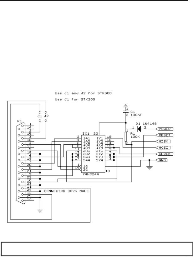
BASCOM supports the STK200 and STK200+ and STK300 ISP programmer from Atmel.
This is a very reliable parallel printer port programmer.
The STK200 ISP programmer is included in the STK200 starter kit.
Most programs were tested with the STK200.
For those who don't have this kit and the programmer the following schematic shows how to make your own programmer:
page -76-

© MCS Electronics, 1995-2007
The dongle has a chip with no identification but since the schematic is all over the web, it is included. MCS also sells a STK200 compatible programmer.
Here is a tip received from a user :
If the parallel port is disconnected from the interface and left floating, the '244 latch outputs will waver, causing your microcontroller to randomly reset during operation. The simple addition of a 100K pull-up resisistor between pin 1 and 20 of the latch, and another between pin 19 and 20, will eliminate this problem. You'll then have HIGH-Z on the latch outputs when the cable is disconnected (as well as when it's connected and you aren't programming), so you can use the MOSI etc. pins for I/O.
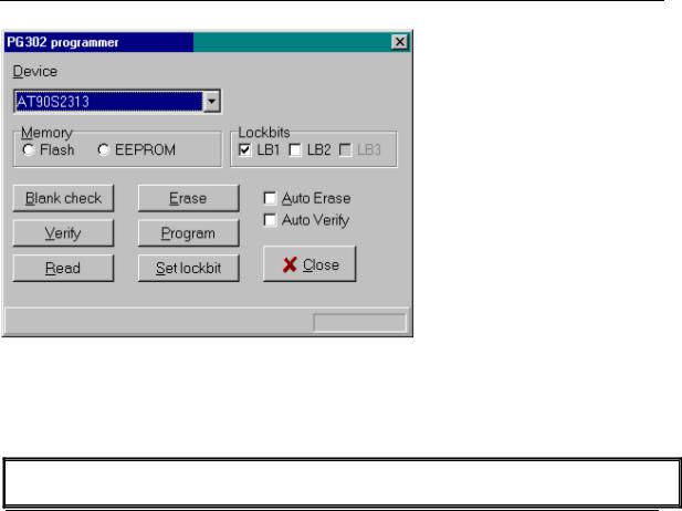
PG302 programmer
The PG302 is a serial programmer. It works and looks exactly as the original PG302 software.
page -77-

© MCS Electronics, 1995-2007
Select the programmer from The Option Programmer menu or right click on the  button to show the Option Programmer menu
Sample Electronics cable programmer
Sample Electronics submitted the simple cable programmer.
They produce professional programmers too. This simple programmer you can make yourself within 10 minutes.
What you need is a DB25 centronics male connector, a flat cable and a connector that can be connected to the target MCU board.
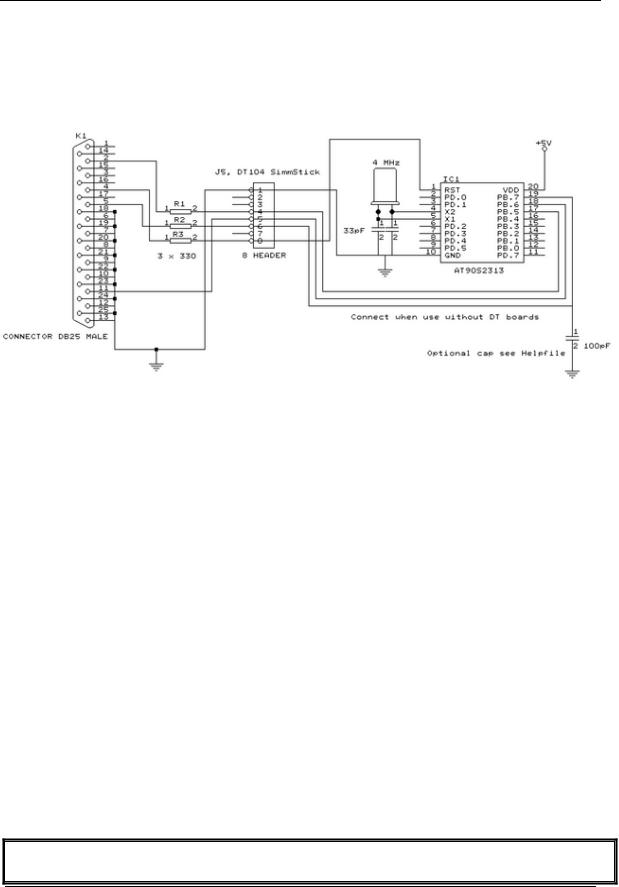
The connections to make are as following:
DB25 pin |
Target MCU |
Target MCU |
Target MCU pin 8515 |
DT104 |
|
pin(AT90S8535) |
M103/M128 |
|
|
2, D0 |
MOSI, pin 6 |
PE.0, 2 |
MOSI, 6 |
J5, pin 4 |
4, D2 |
RESET, pin 9 |
RESET, 20 |
RESET, 9 |
J5, pin 8 |
5, D3 |
CLOCK, pin 8 |
PB.1,11 |
CLOCK, 8 |
J5, pin 6 |
11, BUSY |
MISO, pin 7 |
PE.1, 3 |
MISO, 7 |
J5, pin 5 |
18-25,GND |
GROUND |
GROUND |
GND,20 |
J5, pin 1 |
|
|
|
|
|
The MCU pin numbers are shown for an 8535! And 8515
Note that 18-25 means pins 18,19,20,21,22,23,24 and 25
You can use a small resistor of 100-220 ohm in series with the D0, D2 and D3 line in order not to short circuit your LPT port in the event the MCU pins are high.
It was tested without these resistors and no problems occured.
 Tip : when testing programmers etc. on the LPT it is best to buy an I/O card for your PC that has a LPT port. This way you don’t destroy your LPT port that is on the motherboard in the event you make a mistake!
page -78-

© MCS Electronics, 1995-2007
The following picture shows the connections to make. Both a setup for the DT104 and stand-alone PCB are shown.
I received the following useful information:
I have been having spurious success with the simple cable programmer from Sample Electronics for the AVR series.
After resorting to hooking up the CRO I have figured it out (I think). When trying to identify the chip, no response on the MISO pin indicates that the Programming Enable command has not been correctly received by the target.
The SCK line Mark/Space times were okay but it looked a bit sad with a slow rise time but a rapid fall time. So I initially tried to improve the rise
time with a pull-up. No change ie still could not identify chip. I was about to add some buffers when I came across an Atmel app note for their serial programmer "During this first phase of the programming cycle, keeping the SCK line free from pulses is critical, as pulses will cause the target AVR to loose synchronization with the programmer. When synchronization is lost, the only means of regaining synchronization is to release the RESET line for more than 100ms."
I have added a 100pF cap from SCK to GND and works first time every time now. The SCK rise time is still sad but there must have been enough noise to corrupt the initial command despite using a 600mm shielded cable.
KITSRUS Programmer
The K122 is a KIT from KITSRUS. (www.kitsrus.com)
The programmer supports the most popular 20 and 40 pins AVR chips.
On the Programmer Options tab you must select this programmer and the COM port it is
page -79-
