- •Table of Contents
- •Index
- •Keyword Reference
- •Installation
- •Installation of BASCOM
- •BASCOM IDE
- •Running BASCOM-AVR
- •File New
- •File Close
- •File Save
- •File Save As
- •File Print Preview
- •File Print
- •File Exit
- •View PinOut
- •View PDF viewer
- •View Error Panel
- •Edit Undo
- •Edit Redo
- •Edit Cut
- •Edit Copy
- •Edit Paste
- •Edit Find
- •Edit Find Next
- •Edit Replace
- •Edit Goto
- •Edit Toggle Bookmark
- •Edit Goto Bookmark
- •Edit Indent Block
- •Edit Unindent Block
- •Edit Remark Block
- •Program Compile
- •Program Syntax Check
- •Program Show Result
- •Program Simulate
- •Program Send to Chip
- •Tools Terminal Emulator
- •Tools LCD Designer
- •Tools LIB Manager
- •Tools Graphic Converter
- •Tools Stack Analyzer
- •Tools Plugin Manager
- •Tools Batch Compile
- •Options Compiler
- •Options Compiler Chip
- •Options Compiler Output
- •Options Compiler Communication
- •Options Compiler I2C, SPI, 1WIRE
- •Options Compiler LCD
- •Options Communication
- •Options Environment
- •Options Simulator
- •Options Programmer
- •Supported Programmers
- •ISP programmer
- •PG302 programmer
- •Sample Electronics cable programmer
- •KITSRUS Programmer
- •MCS Universal Interface Programmer
- •STK500 Programmer
- •Lawicel BootLoader
- •AVR ISP Programmer
- •USB-ISP Programmer
- •MCS Bootloader
- •Options Monitor
- •Options Printer
- •Window Cascade
- •Window Tile
- •Window Arrange Icons
- •Window Minimize All
- •Help About
- •Help Index
- •Help MCS Forum
- •Help MCS Shop
- •Help Support
- •Help Knowledge Base
- •Help Credits
- •BASCOM Editor Keys
- •Program Development Order
- •PlugIns
- •Font Editor
- •PinOut
- •BASCOM HARDWARE
- •Additional Hardware
- •AVR Internal Hardware
- •AVR Internal Registers
- •AVR Internal Hardware TIMER0
- •AVR Internal Hardware TIMER1
- •AVR Internal Hardware Watchdog timer
- •AVR Internal Hardware Port B
- •AVR Internal Hardware Port D
- •Adding XRAM
- •Attaching an LCD Display
- •Memory usage
- •Using the 1 WIRE protocol
- •Using the SPI protocol
- •Power Up
- •Chips
- •ATtiny22
- •ATtiny13
- •ATtiny15
- •ATtiny25
- •ATtiny45
- •ATtiny85
- •ATtiny26
- •ATtiny2313
- •ATMEGA8
- •ATMEGA16
- •ATMEGA32
- •ATMEGA48
- •ATMEGA88
- •ATMEGA168
- •ATMEGA64
- •ATMEGA103
- •ATMEGA128
- •ATMEGA161
- •ATMEGA162
- •ATMEGA163
- •ATMEGA165
- •ATMEGA169
- •ATMEGA323
- •ATMEGA603
- •ATMEGA8515
- •ATMEGA8535
- •BASCOM Language Fundamentals
- •Changes compared to BASCOM-8051
- •Language Fundamentals
- •Mixing ASM and BASIC
- •Assembler mnemonics
- •Reserved Words
- •Error Codes
- •Newbie problems
- •Tips and tricks
- •ASCII chart
- •BASCOM Language Reference
- •$BAUD
- •$BAUD1
- •$BOOT
- •$CRYSTAL
- •$DATA
- •$DEFAULT
- •$EEPLEAVE
- •$EEPROM
- •$EEPROMHEX
- •$EXTERNAL
- •$FRAMESIZE
- •$HWSTACK
- •$INCLUDE
- •$INITMICRO
- •$LCDPUTCTRL
- •$LCDPUTDATA
- •$LCDRS
- •$LCDVFO
- •$LOADER
- •$LOADERSIZE
- •$NOCOMP
- •$NOINIT
- •$NORAMCLEAR
- •$PROG
- •$PROGRAMMER
- •$REGFILE
- •$ROMSTART
- •$SERIALINPUT
- •$SERIALINPUT1
- •$SERIALINPUT2LCD
- •$SERIALOUTPUT
- •$SERIALOUTPUT1
- •$SWSTACK
- •$TIMEOUT
- •$TINY
- •$WAITSTATE
- •$XRAMSIZE
- •$XRAMSTART
- •1WIRECOUNT
- •1WRESET
- •1WREAD
- •1WSEARCHFIRST
- •1WSEARCHNEXT
- •1WVERIFY
- •1WWRITE
- •ACOS
- •ALIAS
- •ASIN
- •BASE64DEC
- •BASE64ENC
- •BAUD
- •BAUD1
- •BINVAL
- •BIN2GRAY
- •BITWAIT
- •BITS
- •BLOAD
- •BSAVE
- •BUFSPACE
- •BYVAL
- •CALL
- •CHECKSUM
- •CIRCLE
- •CLEAR
- •CLOCKDIVISION
- •CLOSE
- •CLOSESOCKET
- •CONFIG
- •CONFIG 1WIRE
- •CONFIG ACI
- •CONFIG ADC
- •CONFIG ATEMU
- •CONFIG BCCARD
- •CONFIG CLOCK
- •CONFIG CLOCKDIV
- •CONFIG COM1
- •CONFIG COM2
- •CONFIG COMx
- •CONFIG DATE
- •CONFIG DCF77
- •CONFIG DEBOUNCE
- •CONFIG I2CDELAY
- •CONFIG I2CSLAVE
- •CONFIG INPUT
- •CONFIG INTx
- •CONFIG GRAPHLCD
- •CONFIG KBD
- •CONFIG KEYBOARD
- •CONFIG LCD
- •CONFIG LCDBUS
- •CONFIG LCDMODE
- •CONFIG LCDPIN
- •CONFIG PORT
- •CONFIG PRINT
- •CONFIG PRINTBIN
- •CONFIG PS2EMU
- •CONFIG RC5
- •CONFIG SDA
- •CONFIG SCL
- •CONFIG SERIALIN
- •CONFIG SERIALIN1
- •CONFIG SERIALOUT
- •CONFIG SERIALOUT1
- •CONFIG SINGLE
- •CONFIG SPI
- •CONFIG SERVOS
- •CONFIG TCPIP
- •CONFIG TIMER0
- •CONFIG TIMER1
- •CONFIG TIMER2
- •CONFIG TWI
- •CONFIG TWISLAVE
- •CONFIG WAITSUART
- •CONFIG WATCHDOG
- •CONFIG X10
- •CONFIG XRAM
- •CONST
- •COSH
- •COUNTER0 and COUNTER1
- •CPEEK
- •CPEEKH
- •CRYSTAL
- •CURSOR
- •DATA
- •DAYOFWEEK
- •DAYOFYEAR
- •DATE$
- •DATE
- •DEBUG
- •DEBOUNCE
- •DECR
- •DECLARE FUNCTION
- •DECLARE SUB
- •DEFxxx
- •DEFLCDCHAR
- •DELAY
- •DISABLE
- •DISKFREE
- •DISKSIZE
- •DISPLAY
- •DO-LOOP
- •DriveCheck
- •DriveGetIdentity
- •DriveInit
- •DriveReset
- •DriveReadSector
- •DriveWriteSector
- •DTMFOUT
- •ECHO
- •ELSE
- •ENABLE
- •ENCODER
- •EXIT
- •FILEATTR
- •FILEDATE
- •FILEDATETIME
- •FILELEN
- •FILETIME
- •FLUSH
- •FORMAT
- •FOR-NEXT
- •FOURTHLINE
- •FRAC
- •FREEFILE
- •FUSING
- •GETADC
- •GETATKBD
- •GETATKBDRAW
- •GETDSTIP
- •GETDSTPORT
- •GETKBD
- •GETRC
- •GETRC5
- •GETTCPREGS
- •GETSOCKET
- •GLCDCMD
- •GLCDDATA
- •GOSUB
- •GOTO
- •GRAY2BIN
- •HEXVAL
- •HIGH
- •HIGHW
- •HOME
- •I2CINIT
- •I2CRECEIVE
- •I2CSEND
- •I2START,I2CSTOP, I2CRBYTE, I2CWBYTE
- •IDLE
- •IF-THEN-ELSE-END IF
- •INCR
- •INITFILESYSTEM
- •INITLCD
- •INKEY
- •INPUTBIN
- •INPUTHEX
- •INPUT
- •INSTR
- •ISCHARWAITING
- •KILL
- •LCASE
- •LCDAT
- •LCDCONTRAST
- •LEFT
- •LINE
- •LINE INPUT
- •LTRIM
- •LOAD
- •LOADADR
- •LOADLABEL
- •LOADWORDADR
- •LOCAL
- •LOCATE
- •LOOKDOWN
- •LOOKUP
- •LOOKUPSTR
- •LOWERLINE
- •MAKEBCD
- •MAKEINT
- •MAKEDEC
- •MAKETCP
- •MEMCOPY
- •NBITS
- •ON INTERRUPT
- •ON VALUE
- •OPEN
- •PEEK
- •POKE
- •POPALL
- •POWER
- •POWERDOWN
- •POWERSAVE
- •PRINTBIN
- •PSET
- •PS2MOUSEXY
- •PULSEIN
- •PULSEOUT
- •PUSHALL
- •RC5SEND
- •RC5SENDEXT
- •RC6SEND
- •READ
- •READEEPROM
- •READMAGCARD
- •RESET
- •RESTORE
- •RETURN
- •RIGHT
- •ROTATE
- •ROUND
- •RTRIM
- •SECELAPSED
- •SECOFDAY
- •SEEK
- •SELECT-CASE-END SELECT
- •SETFONT
- •SETTCP
- •SETTCPREGS
- •SENDSCAN
- •SENDSCANKBD
- •SERIN
- •SEROUT
- •SETIPPROTOCOL
- •SHIFT
- •SHIFTCURSOR
- •SHIFTIN
- •SHIFTOUT
- •SHIFTLCD
- •SHOWPIC
- •SHOWPICE
- •SINH
- •SOCKETCONNECT
- •SOCKETLISTEN
- •SOCKETSTAT
- •SONYSEND
- •SOUND
- •SPACE
- •SPIIN
- •SPIINIT
- •SPIMOVE
- •SPIOUT
- •SPLIT
- •START
- •STCHECK
- •STOP
- •STRING
- •SYSSEC
- •SYSSECELAPSED
- •SYSDAY
- •SWAP
- •TCPCHECKSUM
- •TCPREAD
- •TCPWRITE
- •TCPWRITESTR
- •TANH
- •THIRDLINE
- •TIME$
- •TIME
- •TOGGLE
- •TRIM
- •UCASE
- •UDPREAD
- •UDPWRITE
- •UDPWRITESTR
- •UPPERLINE
- •VARPTR
- •VERSION
- •WAIT
- •WAITKEY
- •WAITMS
- •WAITUS
- •WHILE-WEND
- •WRITE
- •WRITEEEPROM
- •X10DETECT
- •X10SEND
- •#IF ELSE ENDIF
- •International Resellers
- •International Resellers
- •ASM Libraries
- •EXTENDED I2C
- •MCSBYTE
- •MCSBYTEINT
- •TCPIP
- •LCD4BUSY
- •GLCD
- •GLCDSED
- •LCD-EPSON
- •AVR-DOS File System
- •CF Card
- •Compact FlashCard Driver
- •Elektor CF-Interface
- •XRAM CF-Interface for simulation
- •New CF-Card Drivers
- •Floating Point
- •FP_TRIG
- •DOUBLE
- •I2C SLAVE
- •I2CSLAVE
- •I2C TWI Slave
- •SPISLAVE
- •DATE TIME
- •EUROTIMEDATE
- •DATETIME
- •PS2-AT Mouse and Keyboard Emulation
- •AT_EMULATOR
- •PS2MOUSE_EMULATOR
- •BCCARD
- •BCCARD
- •BCDEF
- •BCCALL
- •BCRESET
- •Tools
- •LCD RGB-8 Converter

© MCS Electronics, 1995-2007
The settings for the internal hardware UART are:
No parity , 8 data bits , 1 stop bit
Some AVR chips have the option to specify different data bits and different stop bits and parity.
Note that these settings must match the settings of the terminal emulator. In the simulator the output is always shown correct since the baud rate is not taken in consideration during simulation. With real hardware when you print data at 9600 baud, the terminal emulator will show weird characters when not set to the same baud rate, in this example, to 9600 baud.
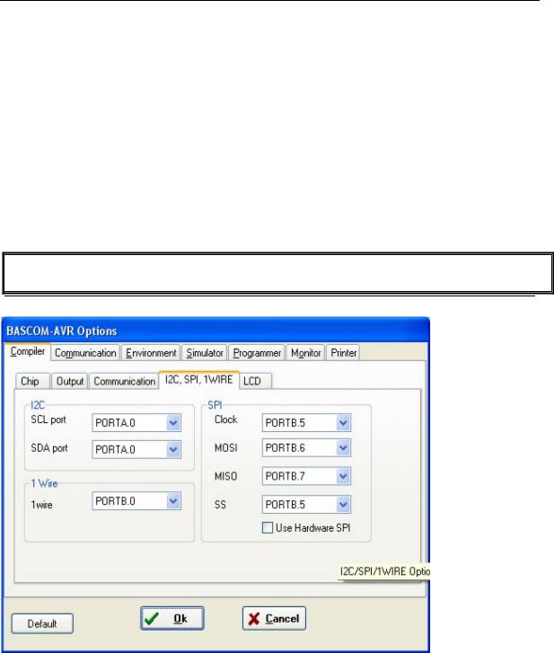
Options Compiler I2C, SPI, 1WIRE
Options Compiler I2C, SPI, 1WIRE
Item |
Description |
SCL port |
Select the port pin that serves as the SCL-line for the I2C related |
|
statements. |
SDA port |
Select the port pin that serves as the SDA-line for the I2C related |
|
statements. |
1WIRE |
Select the port pin that serves as the 1WIRE-line for the 1Wire related |
|
statements. |
Clock |
Select the port pin that serves as the clock-line for the SPI related |
|
statements. |
page -67-

|
© MCS Electronics, 1995-2007 |
|
|
|
|
MOSI |
Select the port pin that serves as the MOSI-line for the SPI related |
|
|
statements. |
|
MISO |
Select the port pin that serves as the MISO-line for the SPI related |
|
|
statements. |
|
SS |
Select the port pin that serves as the SS-line for the SPI related |
|
|
statements. |
|
Use hardware SPI |
Select to use built-in hardware for SPI, otherwise software emulation of |
|
|
SPI will be used. The 2313 does not have internal HW SPI so it can only |
|
|
be used with software spi mode. |
|
|
When you do use harware SPI, the above settings are not used |
|
|
anymore since the SPI pins are dedicated pins and can not be choosen |
|
|
by the user. |
|
|
|
|
It is advised to use the various CONFIG commands in your source code. It make more clear in the source code which pins are used.
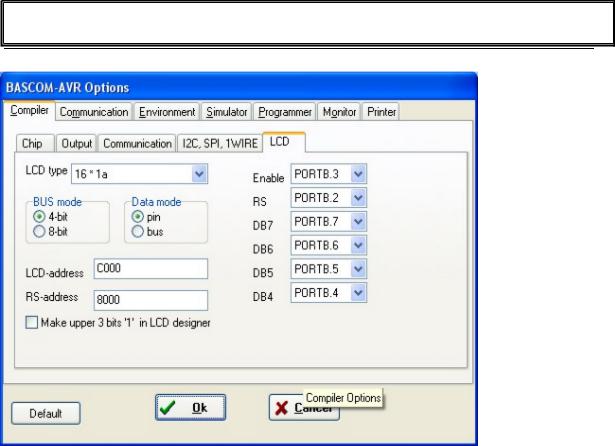
Options Compiler LCD
Options Compiler LCD
Item |
Description |
LCD type |
The LCD display used. |
Bus mode |
The LCD can be operated in BUS mode or in PIN mode. In PIN |
|
mode, the data lines of the LCD are connected to the processor |
|
port pins. In BUS mode the data lines of the LCD are connected |
|
to the data lines of the BUS. |
|
Select 4 when you have only connect DB4-DB7. When the data |
|
mode is 'pin' , you should select 4. |
|
|
page -68-
