
- •Table of Contents
- •Index
- •Keyword Reference
- •Installation
- •Installation of BASCOM
- •BASCOM IDE
- •Running BASCOM-AVR
- •File New
- •File Close
- •File Save
- •File Save As
- •File Print Preview
- •File Print
- •File Exit
- •View PinOut
- •View PDF viewer
- •View Error Panel
- •Edit Undo
- •Edit Redo
- •Edit Cut
- •Edit Copy
- •Edit Paste
- •Edit Find
- •Edit Find Next
- •Edit Replace
- •Edit Goto
- •Edit Toggle Bookmark
- •Edit Goto Bookmark
- •Edit Indent Block
- •Edit Unindent Block
- •Edit Remark Block
- •Program Compile
- •Program Syntax Check
- •Program Show Result
- •Program Simulate
- •Program Send to Chip
- •Tools Terminal Emulator
- •Tools LCD Designer
- •Tools LIB Manager
- •Tools Graphic Converter
- •Tools Stack Analyzer
- •Tools Plugin Manager
- •Tools Batch Compile
- •Options Compiler
- •Options Compiler Chip
- •Options Compiler Output
- •Options Compiler Communication
- •Options Compiler I2C, SPI, 1WIRE
- •Options Compiler LCD
- •Options Communication
- •Options Environment
- •Options Simulator
- •Options Programmer
- •Supported Programmers
- •ISP programmer
- •PG302 programmer
- •Sample Electronics cable programmer
- •KITSRUS Programmer
- •MCS Universal Interface Programmer
- •STK500 Programmer
- •Lawicel BootLoader
- •AVR ISP Programmer
- •USB-ISP Programmer
- •MCS Bootloader
- •Options Monitor
- •Options Printer
- •Window Cascade
- •Window Tile
- •Window Arrange Icons
- •Window Minimize All
- •Help About
- •Help Index
- •Help MCS Forum
- •Help MCS Shop
- •Help Support
- •Help Knowledge Base
- •Help Credits
- •BASCOM Editor Keys
- •Program Development Order
- •PlugIns
- •Font Editor
- •PinOut
- •BASCOM HARDWARE
- •Additional Hardware
- •AVR Internal Hardware
- •AVR Internal Registers
- •AVR Internal Hardware TIMER0
- •AVR Internal Hardware TIMER1
- •AVR Internal Hardware Watchdog timer
- •AVR Internal Hardware Port B
- •AVR Internal Hardware Port D
- •Adding XRAM
- •Attaching an LCD Display
- •Memory usage
- •Using the 1 WIRE protocol
- •Using the SPI protocol
- •Power Up
- •Chips
- •ATtiny22
- •ATtiny13
- •ATtiny15
- •ATtiny25
- •ATtiny45
- •ATtiny85
- •ATtiny26
- •ATtiny2313
- •ATMEGA8
- •ATMEGA16
- •ATMEGA32
- •ATMEGA48
- •ATMEGA88
- •ATMEGA168
- •ATMEGA64
- •ATMEGA103
- •ATMEGA128
- •ATMEGA161
- •ATMEGA162
- •ATMEGA163
- •ATMEGA165
- •ATMEGA169
- •ATMEGA323
- •ATMEGA603
- •ATMEGA8515
- •ATMEGA8535
- •BASCOM Language Fundamentals
- •Changes compared to BASCOM-8051
- •Language Fundamentals
- •Mixing ASM and BASIC
- •Assembler mnemonics
- •Reserved Words
- •Error Codes
- •Newbie problems
- •Tips and tricks
- •ASCII chart
- •BASCOM Language Reference
- •$BAUD
- •$BAUD1
- •$BOOT
- •$CRYSTAL
- •$DATA
- •$DEFAULT
- •$EEPLEAVE
- •$EEPROM
- •$EEPROMHEX
- •$EXTERNAL
- •$FRAMESIZE
- •$HWSTACK
- •$INCLUDE
- •$INITMICRO
- •$LCDPUTCTRL
- •$LCDPUTDATA
- •$LCDRS
- •$LCDVFO
- •$LOADER
- •$LOADERSIZE
- •$NOCOMP
- •$NOINIT
- •$NORAMCLEAR
- •$PROG
- •$PROGRAMMER
- •$REGFILE
- •$ROMSTART
- •$SERIALINPUT
- •$SERIALINPUT1
- •$SERIALINPUT2LCD
- •$SERIALOUTPUT
- •$SERIALOUTPUT1
- •$SWSTACK
- •$TIMEOUT
- •$TINY
- •$WAITSTATE
- •$XRAMSIZE
- •$XRAMSTART
- •1WIRECOUNT
- •1WRESET
- •1WREAD
- •1WSEARCHFIRST
- •1WSEARCHNEXT
- •1WVERIFY
- •1WWRITE
- •ACOS
- •ALIAS
- •ASIN
- •BASE64DEC
- •BASE64ENC
- •BAUD
- •BAUD1
- •BINVAL
- •BIN2GRAY
- •BITWAIT
- •BITS
- •BLOAD
- •BSAVE
- •BUFSPACE
- •BYVAL
- •CALL
- •CHECKSUM
- •CIRCLE
- •CLEAR
- •CLOCKDIVISION
- •CLOSE
- •CLOSESOCKET
- •CONFIG
- •CONFIG 1WIRE
- •CONFIG ACI
- •CONFIG ADC
- •CONFIG ATEMU
- •CONFIG BCCARD
- •CONFIG CLOCK
- •CONFIG CLOCKDIV
- •CONFIG COM1
- •CONFIG COM2
- •CONFIG COMx
- •CONFIG DATE
- •CONFIG DCF77
- •CONFIG DEBOUNCE
- •CONFIG I2CDELAY
- •CONFIG I2CSLAVE
- •CONFIG INPUT
- •CONFIG INTx
- •CONFIG GRAPHLCD
- •CONFIG KBD
- •CONFIG KEYBOARD
- •CONFIG LCD
- •CONFIG LCDBUS
- •CONFIG LCDMODE
- •CONFIG LCDPIN
- •CONFIG PORT
- •CONFIG PRINT
- •CONFIG PRINTBIN
- •CONFIG PS2EMU
- •CONFIG RC5
- •CONFIG SDA
- •CONFIG SCL
- •CONFIG SERIALIN
- •CONFIG SERIALIN1
- •CONFIG SERIALOUT
- •CONFIG SERIALOUT1
- •CONFIG SINGLE
- •CONFIG SPI
- •CONFIG SERVOS
- •CONFIG TCPIP
- •CONFIG TIMER0
- •CONFIG TIMER1
- •CONFIG TIMER2
- •CONFIG TWI
- •CONFIG TWISLAVE
- •CONFIG WAITSUART
- •CONFIG WATCHDOG
- •CONFIG X10
- •CONFIG XRAM
- •CONST
- •COSH
- •COUNTER0 and COUNTER1
- •CPEEK
- •CPEEKH
- •CRYSTAL
- •CURSOR
- •DATA
- •DAYOFWEEK
- •DAYOFYEAR
- •DATE$
- •DATE
- •DEBUG
- •DEBOUNCE
- •DECR
- •DECLARE FUNCTION
- •DECLARE SUB
- •DEFxxx
- •DEFLCDCHAR
- •DELAY
- •DISABLE
- •DISKFREE
- •DISKSIZE
- •DISPLAY
- •DO-LOOP
- •DriveCheck
- •DriveGetIdentity
- •DriveInit
- •DriveReset
- •DriveReadSector
- •DriveWriteSector
- •DTMFOUT
- •ECHO
- •ELSE
- •ENABLE
- •ENCODER
- •EXIT
- •FILEATTR
- •FILEDATE
- •FILEDATETIME
- •FILELEN
- •FILETIME
- •FLUSH
- •FORMAT
- •FOR-NEXT
- •FOURTHLINE
- •FRAC
- •FREEFILE
- •FUSING
- •GETADC
- •GETATKBD
- •GETATKBDRAW
- •GETDSTIP
- •GETDSTPORT
- •GETKBD
- •GETRC
- •GETRC5
- •GETTCPREGS
- •GETSOCKET
- •GLCDCMD
- •GLCDDATA
- •GOSUB
- •GOTO
- •GRAY2BIN
- •HEXVAL
- •HIGH
- •HIGHW
- •HOME
- •I2CINIT
- •I2CRECEIVE
- •I2CSEND
- •I2START,I2CSTOP, I2CRBYTE, I2CWBYTE
- •IDLE
- •IF-THEN-ELSE-END IF
- •INCR
- •INITFILESYSTEM
- •INITLCD
- •INKEY
- •INPUTBIN
- •INPUTHEX
- •INPUT
- •INSTR
- •ISCHARWAITING
- •KILL
- •LCASE
- •LCDAT
- •LCDCONTRAST
- •LEFT
- •LINE
- •LINE INPUT
- •LTRIM
- •LOAD
- •LOADADR
- •LOADLABEL
- •LOADWORDADR
- •LOCAL
- •LOCATE
- •LOOKDOWN
- •LOOKUP
- •LOOKUPSTR
- •LOWERLINE
- •MAKEBCD
- •MAKEINT
- •MAKEDEC
- •MAKETCP
- •MEMCOPY
- •NBITS
- •ON INTERRUPT
- •ON VALUE
- •OPEN
- •PEEK
- •POKE
- •POPALL
- •POWER
- •POWERDOWN
- •POWERSAVE
- •PRINTBIN
- •PSET
- •PS2MOUSEXY
- •PULSEIN
- •PULSEOUT
- •PUSHALL
- •RC5SEND
- •RC5SENDEXT
- •RC6SEND
- •READ
- •READEEPROM
- •READMAGCARD
- •RESET
- •RESTORE
- •RETURN
- •RIGHT
- •ROTATE
- •ROUND
- •RTRIM
- •SECELAPSED
- •SECOFDAY
- •SEEK
- •SELECT-CASE-END SELECT
- •SETFONT
- •SETTCP
- •SETTCPREGS
- •SENDSCAN
- •SENDSCANKBD
- •SERIN
- •SEROUT
- •SETIPPROTOCOL
- •SHIFT
- •SHIFTCURSOR
- •SHIFTIN
- •SHIFTOUT
- •SHIFTLCD
- •SHOWPIC
- •SHOWPICE
- •SINH
- •SOCKETCONNECT
- •SOCKETLISTEN
- •SOCKETSTAT
- •SONYSEND
- •SOUND
- •SPACE
- •SPIIN
- •SPIINIT
- •SPIMOVE
- •SPIOUT
- •SPLIT
- •START
- •STCHECK
- •STOP
- •STRING
- •SYSSEC
- •SYSSECELAPSED
- •SYSDAY
- •SWAP
- •TCPCHECKSUM
- •TCPREAD
- •TCPWRITE
- •TCPWRITESTR
- •TANH
- •THIRDLINE
- •TIME$
- •TIME
- •TOGGLE
- •TRIM
- •UCASE
- •UDPREAD
- •UDPWRITE
- •UDPWRITESTR
- •UPPERLINE
- •VARPTR
- •VERSION
- •WAIT
- •WAITKEY
- •WAITMS
- •WAITUS
- •WHILE-WEND
- •WRITE
- •WRITEEEPROM
- •X10DETECT
- •X10SEND
- •#IF ELSE ENDIF
- •International Resellers
- •ASM Libraries
- •EXTENDED I2C
- •MCSBYTE
- •MCSBYTEINT
- •TCPIP
- •LCD4BUSY
- •GLCD
- •GLCDSED
- •LCD-EPSON
- •AVR-DOS File System
- •CF Card
- •Compact FlashCard Driver
- •Elektor CF-Interface
- •XRAM CF-Interface for simulation
- •New CF-Card Drivers
- •Floating Point
- •FP_TRIG
- •DOUBLE
- •I2C SLAVE
- •I2CSLAVE
- •I2C TWI Slave
- •SPISLAVE
- •DATE TIME
- •EUROTIMEDATE
- •DATETIME
- •PS2-AT Mouse and Keyboard Emulation
- •AT_EMULATOR
- •PS2MOUSE_EMULATOR
- •BCCARD
- •BCCARD
- •BCDEF
- •BCCALL
- •BCRESET
- •Tools
- •LCD RGB-8 Converter

© MCS Electronics, 1995-2007
GETRC
Action
Retrieves the value of a resistor or a capacitor.
Syntax
var = GETRC( pin , number )
Remarks
Var |
The word variable that is assigned with the value. |
Pin |
The PIN name for the R/C is connection. |
Number |
The port pin for the R/C is connection. |
|
|
The name of the input port (PIND for example) must be passed even when allthe other pins are configured for output. The pin number must also be passed. This may be a constant or a variable.
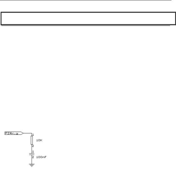
A circuit is shown below:
The capacitor is charged and the time it takes to discharge it is measured and stored in the variable. Now when you vary either the resistor or the capacitor, different values will be returned. This function is intended to return a relative position of a resistor wiper, not to return the value of the resistor. But with some calculations it can be retrieved.
See also
NONE
Example
'----------------------------------------------------------------------------- |
|
------------ |
: getrc.bas |
'name |
|
'copyright |
: (c) 1995-2005, MCS Electronics |
'purpose |
: demonstrates how to get the value of a resistor |
'micro |
: AT90S8535 |
'suited for demo |
: yes |
'commercial addon needed |
: no |
'The library also shows how to pass a variable for use with individual port
'pins. This is only possible in the AVR architecture and not in the 8051
'-----------------------------------------------------------------------------
------------
page -510-

|
© MCS Electronics, 1995-2007 |
$regfile = "8535def.dat" |
' specify the used |
micro |
' used crystal |
$crystal = 4000000 |
|
frequency |
' use baud rate |
$baud = 19200 |
|
$hwstack = 32 |
' default use 32 |
for the hardware stack |
' default use 10 |
$swstack = 10 |
|
for the SW stack |
' default use 40 |
$framesize = 40 |
|
for the frame space |
|
'The function works by charging a capacitor and uncharge it little by little 'A word counter counts until the capacitor is uncharged.
'So the result is an indication of the position of a pot meter not the actual 'resistor value
'This example used the 8535 and a 10K ohm variable resistor connected to PIND.4
'The other side of the resistor is connected to a capacitor of 100nF. 'The other side of the capacitor is connected to ground.
'This is different than BASCOM-8051 GETRC! This because the architecture is different.
'The result of getrc() is a word so DIM one
Dim W As Word
Do
'the first parameter is the PIN register.
'the second parameter is the pin number the resistor/capacitor is connected to
'it could also be a variable! W = Getrc(pind , 4)
Print W
Wait 1
Loop
GETRC5
Action
Retrieves the RC5 remote code from a IR transmitter.
Syntax
GETRC5( address, command )
Uses
TIMER0
Remarks
address |
The RC5 address |
command |
The RC5 command. |
|
|
This statement is based on the AVR 410 application note. Since a timer is needed for accurate delays and background processing TIMER0 is used by this statement.
page -511-

© MCS Electronics, 1995-2007
Also the interrupt of TIMER0 is used by this statement.
TIMER0 can be used by your application since the values are preserved by the statement but a delay can occur. The interrupt can not be reused.
GETRC5 supports extended RC5 code reception.
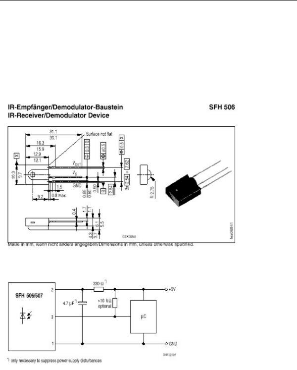
The SFH506-36 is used from Siemens. Other types can be used as well. The TSOP1736 has been tested with success.
For a good operation use the following values for the filter.
Most audio and video systems are equipped with an infra-red remote control.
The RC5 code is a 14-bit word bi-phase coded signal.
The two first bits are start bits, always having the value 1.
The next bit is a control bit or toggle bit, which is inverted every time a button is pressed on the remote control transmitter.
Five system bits hold the system address so that only the right system responds to the code.
Usually, TV sets have the system address 0, VCRs the address 5 and so on. The command sequence is six bits long, allowing up to 64 different commands per address.
The bits are transmitted in bi-phase code (also known as Manchester code).
page -512-

© MCS Electronics, 1995-2007
For extended RC5 code, the extended bit is bit 6 of the command.
The toggle bit is stored in bit 7 of the command.
See also
CONFIG RC5 , RC5SEND, RC6SEND
Example
'----------------------------------------------------------------------------- |
|
------------ |
: rc5.bas |
'name |
|
'copyright |
: (c) 1995-2005, MCS Electronics |
'purpose |
: based on Atmel AVR410 application note |
'micro |
: 90S2313 |
'suited for demo |
: yes |
'commercial addon needed |
: no |
'-----------------------------------------------------------------------------
------------
$regfile = "2313def.dat" |
' specify the used |
micro |
' used crystal |
$crystal = 4000000 |
|
frequency |
' use baud rate |
$baud = 19200 |
|
$hwstack = 32 |
' default use 32 |
for the hardware stack |
' default use 10 |
$swstack = 10 |
|
for the SW stack |
' default use 40 |
$framesize = 40 |
|
for the frame space |
|
'use byte library for smaller code $lib "mcsbyte.lbx"
'This example shows how to decode RC5 remote control signals 'with a SFH506-35 IR receiver.
'Connect to input to PIND.2 for this example
'The GETRC5 function uses TIMER0 and the TIMER0 interrupt.
'The TIMER0 settings are restored however so only the interrupt can not 'be used anymore for other tasks
'tell the compiler which pin we want to use for the receiver input
Config Rc5 = Pind.2
'the interrupt routine is inserted automatic but we need to make it occur 'so enable the interrupts
Enable Interrupts
'reserve space for variables
Dim Address As Byte , Command As Byte Print "Waiting for RC5..."
Do
'now check if a key on the remote is pressed 'Note that at startup all pins are set for INPUT 'so we dont set the direction here
'If the pins is used for other input just unremark the next line
page -513-