


Chapter 6 - Samples
Previous page |
Table of contents |
Chapter overview |
Next page |
CHAPTER 6
The Samples
Introduction
6.1 Supplying the microcontroller
6.2 Macros used in programs
●Macros WAIT, WAITX
●Macro PRINT
6.3 Samples
●Light-emitting diodes - LEDs
●Keyboard
●Optocoupler
Optocouplering the input lines
Optocouplering the output lines
●Relays
●Generating a sound
●Shift registers
Input shift register
Output shift register
●7-segment Displays (multiplexing)
●LCD display
●12-bit AD converter
●Serial communication
Introduction
Examples given in this chapter will show you how to connect the PIC microcontroller with other peripheral components or devices when developing your own microcontroller system. Each example contains detailed description of the hardware part with electrical outline and comments about the program. All programs can be taken directly from the from 'MikroElektronika' internet presentation.
Supplying the microcontroller
Generally speaking, the correct voltage supply is of utmost importance for the proper functioning of the microcontroller system. It can easily be compared to a man breathing in the air. It is more
http://www.mikroelektronika.co.yu/english/product/books/PICbook/6_01Poglavlje.htm (1 of 2) [4/2/2003 16:18:40]
Chapter 6 - Samples
likely that a man who is breathing in fresh air will live longer than a man who's living in a polluted environment.
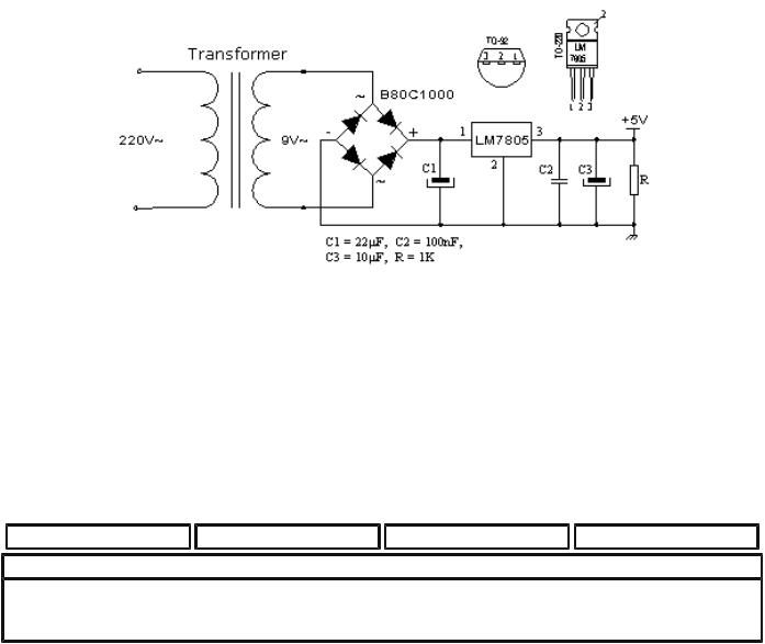
For a proper function of any microcontroller, it is necessary to provide a stable source of supply, a sure reset when you turn it on and an oscillator. According to technical specifications by the manufacturer of PIC microcontroller, supply voltage should move between 2.0V to 6.0V in all versions. The simplest solution to the source of supply is using the voltage stabilizer LM7805 which gives stable +5V on its output. One such source is shown in the picture below.
In order to function properly, or in order to have stable 5V at the output (pin 3), input voltage on pin 1 of LM7805 should be between 7V through 24V. Depending on current consumption of device we will use the appropriate type of voltage stabilizer LM7805. There are several versions of LM7805. For current consumption of up to 1A we should use the version in TO-220 case with the capability of additional cooling. If the total consumption is 50mA, we can use 78L05 (stabilizer version in small TO - 92 packaging for current of up to 100mA).
Previous page |
Table of contents |
Chapter overview |
Next page |
© Copyright 1999. mikroElektronika. All Rights Reserved. For any comments contact webmaster.
http://www.mikroelektronika.co.yu/english/product/books/PICbook/6_01Poglavlje.htm (2 of 2) [4/2/2003 16:18:40]

Chapter 6 - Samples
Previous page |
Table of contents |
Chapter overview |
Next page |
Macros used in programs
Examples given in the following sections of this chapter often use macros WAIT, WAITX and PRINT, so they will be explained in more detail.
Macros WAIT, WAITX
File Wait.inc contains two macros WAIT and WAITX. Through these macros it is possible to assign time delays in different intervals. Both macros use the overflow of counter TMR0 as a basic interval. By changing the prescaler we can change the length of the overflow interval of the counter TMR0.
http://www.mikroelektronika.co.yu/english/product/books/PICbook/6_02Poglavlje.htm (1 of 4) [4/2/2003 16:18:43]
Chapter 6 - Samples
If we use the oscillator (resonator) of 4MHz, for prescaler values 0, 1, and 7 that divide the basic clock of the oscillator, the interval followed by an overflow of timer TMR0 will be 0.512, 1.02 and 65.3 mS. Practically, that means that the biggest delay would be 256x65.3mS which is equal to 16.72 seconds.
In order to use macros in the main program it is necessary do declare variables wcycle and prescWAIT as will be done in examples which follow in this chapter.
Macro WAIT has one argument. The standard value assigned to prescaler of this macro is 1 (1.02mS), and it can not be changed.
WAIT timeconst_1
timeconst_1 is number from 0 to 255. By multiplying that number with the overflow time period we get the total amount of the delay: TIME=timeconst_1 x 1.02mS.
Example: WAIT .100
Example shows how to make a delay of 100x1.02mS, or total of 102mS.
Unlike macro WAIT, macro WAITX has one more argument that can assign prescaler value. Macro WAITX has two arguments:
Timeconst_2 is number from 0 to 255. By multiplying that number with the overflow time period we get the total amount of the delay:
TIME=timeconst_1 x 1.02mS x PRESCext
PRESCext is number from 0 to 7 which sets up the relationship between a clock and timer TMR0.
Example: WAITX .100,7
Example shows how to make a delay of 100x65.3 mS, or total of 653mS.
Macro PRINT
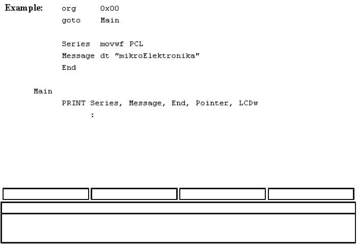
Macro PRINT is found in Print.inc file. It makes it easy to show a string of data on one of the output devices such as : LCD, RS232, matrix printer...etc. The easiest way to form a series is by using a dt (define table) directive. This instruction stores a series of data into program memory as a group of retlw instructions whose operand is data from the string.
http://www.mikroelektronika.co.yu/english/product/books/PICbook/6_02Poglavlje.htm (2 of 4) [4/2/2003 16:18:43]

Chapter 6 - Samples
How one such sequence is formed by using dt instruction is shown in the following example:
org 0x00 goto Main
String movwf PCL
String1 dt "this is 'ASCII' string"
String2 dt "Second string"
End
Main
movlw .5 call String
:
First instruction after label Main writes the position of a member of the string in w register. We jump with instruction call onto label string where position of a member of the string is added to the value of the program counter: PCL=PCL+W. Next we will have in the program counter an address of retlw instruction with the desired member of the string. When this instruction is executed, member of the string will be in w register, and address of the instruction that executed after the call instruction will be in the program counter. End label is an elegant way to mark the address at which the string ends.
Macro PRINT has five arguments:
PRINT macro Addr, Start, End, Var, Out
Addr is an address where one or more strings (which follow one by one) begin. Start is an address of the first member of the string
End is an address where the string ends
Var is the variable which has a role of showing (pointing ) the members of the string
Out is an argument we use to send the address of existing subprograms assigned to output devices such as : LCD, RS-232, etc.
http://www.mikroelektronika.co.yu/english/product/books/PICbook/6_02Poglavlje.htm (3 of 4) [4/2/2003 16:18:43]
Chapter 6 - Samples
Macro PRINT writes out a string of ASCII caracters for 'MikroElektronika' on LCD display. The string takes up one part of program memory beginning at address 0x03.
Previous page |
Table of contents |
Chapter overview |
Next page |
© Copyright 1999. mikroElektronika. All Rights Reserved. For any comments contact webmaster.
http://www.mikroelektronika.co.yu/english/product/books/PICbook/6_02Poglavlje.htm (4 of 4) [4/2/2003 16:18:43]