

Digital design with CPLD applications and VHDL (R. Dueck, 2000)
.pdf

364 C H A P T E R 9 • Counters and Shift Registers
•Draw a timing diagram showing the operation of a serial shift register.
•Draw the logic circuit of a general parallel-load shift register.
•Draw a timing diagram showing the operation of a parallel-load shift register.
•Draw the general logic circuit of a bidirectional shift register and explain the concepts of right-shift and left-shift.
•Use timing diagrams to explain the operation of a bidirectional shift register.
•Describe the operation of a universal shift register.
•Design shift registers, ring counters, and Johnson counters with the MAX PLUS II Graphic Editor or VHDL.
•Verify the operation of shift registers, ring counters, and Johnson counters using the MAX PLUS II simulation tool.
•Design a decoder for a Johnson counter.
•Use a ring counter or a Johnson counter as an event sequencer.
•Compare binary, ring, and Johnson counters in terms of the modulus and the required decoding for each circuit.
Counters and shift registers are two important classes of sequential circuits. In the simplest terms, a counter is a circuit that counts pulses. As such, it is used in many circuit applications, such as event counting and sequencing, timing, frequency division, and control. A basic counter can be enhanced to incorporate functions such as synchronous or asynchronous parallel loading, synchronous or asynchronous clear, count enable, directional control, and output decoding. In this chapter, we will design counters using schematic entry, VHDL, and counters from the Library of Parameterized Modules and ver-
ify their operation using the MAX PLUS II simulator.
Shift registers are circuits that store and move data. They can be used in serial data transfer, serial/parallel conversion, arithmetic functions, and delay elements. As with counters, many shift registers have additional functions such as parallel load, clear, and directional control. We can implement these circuits using schematic entry, VHDL, and LPM components. ■
9.1 Basic Concepts of Digital Counters
K E Y T E R M S
Counter A sequential digital circuit whose output progresses in a predictable repeating pattern, advancing by one state for each clock pulse.
Recycle To make a transition from the last state of the count sequence to the first state.
Count sequence The specific series of output states through which a counter progresses.
State diagram A diagram showing the progression of states of a sequential circuit.
Modulus The number of states through which a counter sequences before repeating.
Modulo-n (or mod-n) counter A counter with a modulus of n.
UP counter A counter with an ascending sequence.
DOWN counter A counter with a descending sequence.

|
|
|
|
|
|
|
|
9.1 • Basic Concepts of Digital Counters |
365 |
|||||||||||
|
The simplest definition of a counter is “a circuit that counts pulses.” Knowing only this, let |
|||||||||||||||||||
|
us look at an example of how we might use a counter circuit. |
|
||||||||||||||||||
|
|
|
|
|
|
|
|
|
|
|
|
|
|
|
|
|
|
|
|
|
EXAMPLE 9.1 |
Figure 9.1 shows a 10-bit binary counter that can be used to count the number of people |
|||||||||||||||||||
|
passing by an optical sensor. Every time the sensor detects a person passing by, it produces |
|||||||||||||||||||
|
a pulse. Briefly describe the counter’s operation. What is the maximum number of people |
|||||||||||||||||||
|
it can count? What happens if this number is exceeded? |
|
||||||||||||||||||
FIGURE 9.1 |
|
|
|
|
|
|
|
|
|
|
|
|
|
|
|
|
|
|
|
|
|
|
|
|
|
|
|
|
|
|
CTR DIV 1024 |
|
|
||||||||
Example 9.1 |
|
|
|
|
|
|
|
|
|
|
|
|
||||||||
|
Optical |
|
|
|
|
|
|
|
|
|
|
|
|
|
|
|
|
|
|
|
10-bit Counter |
|
|
|
|
|
|
|
CLK |
|
|
||||||||||
|
|
|
|
|
|
|
|
|
||||||||||||
|
|
sensor |
|
|
|
|
|
|
|
|
||||||||||
|
|
|
|
|
|
|
|
|
|
|
|
|
|
|
|
|
|
|
|
|
|
|
|
|
|
|
|
|
Q9 Q8 Q7 Q6 Q5 Q4 Q3 Q2 Q1 Q0 |
|
|
||||||||||
|
|
|
|
|
|
|
|
|
|
|||||||||||
|
|
|
|
|
|
|
|
|
|
|
|
|
|
|
|
|
|
|
|
|
|
|
|
|
|
|
|
|
|
|
|
|
|
|
|
|
|
|
|
|
|
Solution The counter has a 10-bit output, allowing a binary number from 00 0000 0000 to 11 1111 1111 (0 to 1023) to appear at its output. The sensor causes the counter to advance by one binary number for every pulse applied to the counter’s clock (CLK) input. If the counter is allowed to register no people (i.e., 00 0000 0000), then the circuit can count 1023 people, since there are 1024 unique binary combinations of a 10-bit number, including 0. (This is because 210 1024.) When the 1024th pulse is applied to the clock input, the counter rolls over to 0 (or recycles) and starts counting again. (After this point, the counter would not accurately reflect the number of people counted.)
The counter is labeled CTR DIV 1024 to indicate that one full cycle of the counter requires 1024 clock pulses (i.e., the frequency of the MSB output signal (Q9) is the clock frequency divided by 1024).
A counter is a digital circuit that has a number of binary outputs whose states progress through a fixed sequence. This count sequence can be ascending, descending, or nonlinear.
The output sequence of a counter is usually defined by its modulus, that is, the number of states through which the counter progresses. An UP counter with a modulus of 12 counts through 12 states from 0000 up to 1011 (0 to 11 in decimal), recycles to 0000, and continues. A DOWN counter with a modulus of 12 counts from 1011 down to 0000, recycles to 1011, and continues downward. Both types of counter are called modulo-12, or just mod-12 counters, since they both have sequences of 12 states.
State Diagram
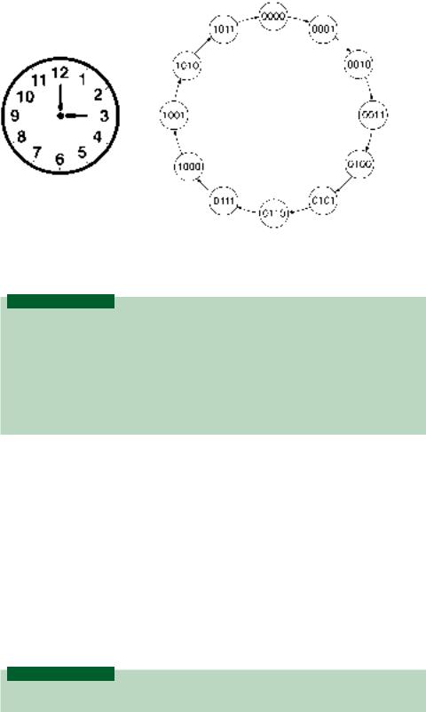
The states of a counter can be represented by a state diagram. Figure 9.2 compares the state diagram of a mod-12 UP counter to an analog clock face. Each counter state is illustrated in the state diagram by a circle containing its binary value. The progression is shown by a series of directional arrows.
Both the clock face and the state diagram represent a closed system of counting. In each case, when we reach the end of the count sequence, we start over from the beginning of the cycle.
For instance, if it is 10:00 a.m. and we want to meet a friend in four hours, we know we should turn up for the appointment at 2:00 p.m. We arrive at this figure by starting at 10 on the clock face and counting 4 digits forward in a “clockwise” circle. This takes us two digits past 12, the “recycle point” of the clock face.
Similarly, if we want to know the 8th state after 0111 in a mod-12 UP counter, we start at state 0111 and count 8 positions in the direction of the arrows. This brings us to state 0000 (the recycle point) in 5 counts and then on to state 0011 in another 3 counts.
366 C H A P T E R 9 • Counters and Shift Registers
FIGURE 9.2
Mod-12 State Diagram and
Analog Clock Face
Number of Bits and Maximum Modulus
K E Y T E R M S
Maximum modulus (mmax) The largest number of counter states that can be represented by n bits (mmax 2n).
Full-sequence counter A counter whose modulus is the same as its maximum modulus (m 2n for an n-bit counter).
Binary counter A counter that generates a binary count sequence.
Truncated-sequence counter A counter whose modulus is less than its maximum modulus (m 2n for an n-bit counter).
The state diagram of Figure 9.2 represents the states of a mod-12 counter as a series of 4- bit numbers. Counter states are always written with a fixed number of bits, since each bit represents the logic level of a physical location in the counter circuit. A mod-12 counter requires four bits because its highest count value is a 4-bit number: 1011.
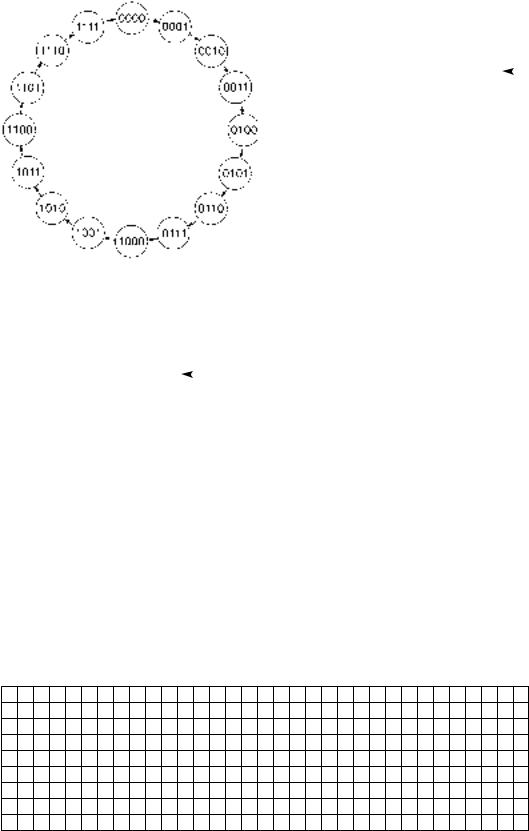
The maximum modulus of a 4-bit counter is 16 ( 24). The count sequence of a mod16 UP counter is from 0000 to 1111 (0 to 15 in decimal), as illustrated in the state diagram of Figure 9.3.
In general, an n-bit counter has a maximum modulus of 2n and a count sequence from
0 to 2n 1 (i.e., all 0s to all 1s). Since a mod-16 counter has a modulus of 2n ( mmax), we say that it is a full-sequence counter. We can also call this a binary counter if it generates
the sequence in binary order. A counter, such as a mod-12 counter, whose modulus is less than 2n, is called a truncated sequence counter.
Count-Sequence Table and Timing Diagram
K E Y T E R M S
Count-sequence table A list of counter states in the order of the count sequence.
Two ways to represent a count sequence other than a state diagram are by a count sequence table and by a timing diagram. The count sequence table is simply a list of counter states in the same order as the count sequence. Tables 9.1 and 9.2 show the count sequence tables of a mod-16 UP counter and a mod-12 UP counter, respectively.
9.1 |
• Basic Concepts of Digital Counters |
367 |
||||||||
FIGURE 9.3 |
|
Table 9.1 Mod-16 |
|
|||||||
State Diagram of a Mod-16 |
|
Count Sequence Table |
|
|||||||
Counter |
|
|
|
|
|
|
||||
|
Q3Q2Q1Q0 |
|
||||||||
|
|
|
|
|
|
|
||||
|
|
|
|
|
|
|
|
|
|
|
|
|
|
|
|
0000 |
|
|
|
|
|
|
|
|
|
|
|
|
|
|
||
|
|
|
|
|
0001 |
|
|
|
|
|
|
|
|
|
|
0010 |
|
|
|
|
|
|
|
|
|
|
0011 |
|
|
|
|
|
|
|
|
|
|
0100 |
|
|
|
|
|
|
|
|
|
|
0101 |
|
|
|
|
|
|
|
|
|
|
0110 |
|
|
|
|
|
|
|
|
|
|
0111 |
|
|
|
|
|
|
|
|
|
|
1000 |
|
|
|
|
|
|
|
|
|
|
1001 |
|
|
|
|
|
|
|
|
|
|
1010 |
|
|
|
|
|
|
|
|
|
|
1011 |
|
|
|
|
|
|
|
|
|
|
1100 |
|
|
|
|
|
|
|
|
|
|
1101 |
|
|
|
|
|
|
|
|
|
|
1110 |
|
|
|
|
|
|
Table 9.2 Mod-12 |
1111 |
|
|
|
|
||||
|
|
|
|
|
||||||
|
|
|
|
|
|
|
||||
|
|
|
|
|
|
|||||
|
Count-Sequence Table |
|
|
|
|
|
|
|||
|
|
|
|
|
|
|
|
|
|
|
|
Q3Q2Q1Q0 |
|
|
|
|
|
|
|||
|
|
|
|
|
|
|
|
|
|
|
0000 |
|
|
|
|
|
|
|
|
|
|
|
|
|
|
|
|
|
|
|
||
0001 |
|
|
|
|
|
|
|
|
|
|
0010 |
|
|
|
|
|
|
|
|
|
|
0011 |
|
|
|
|
|
|
|
|
|
|
0100 |
|
|
|
|
|
|
|
|
|
|
0101 |
|
|
|
|
|
|
|
|
|
|
0110 |
|
|
|
|
|
|
|
|
|
|
0111 |
|
|
|
|
|
|
|
|
|
|
1000 |
|
|
|
|
|
|
|
|
|
|
1001 |
|
|
|
|
|
|
|
|
|
|
1010 |
|
|
|
|
|
|
|
|
|
|
1011 |
|
|
|
|
|
|
|
|
|
|
|
|
|
|
|
|
|
|
|
||
|
|
|
|
|
|
|
|
|
|
|
We can derive timing diagrams from each of these tables. We know that each counter advances by one state with each applied clock pulse. The mod-16 count sequence shows us that the Q0 waveform changes state with each clock pulse. Q1 changes with every two clock pulses, Q2 with every four, and Q3 with every eight. Figure 9.4 shows this pattern for the mod-16 UP counter, assuming the counter is a positive edgetriggered device.
CLK
Q0
Q1
Q2
Q3
FIGURE 9.4
Mod-16 Timing Diagram
368 C H A P T E R 9 • Counters and Shift Registers
|
CLK |
|
|
|
|
|
|
|
|
|
|
|
|
|
|
|
|
|
|
|
|
|
|
|
|
|
|
|
Q0 |
|
|
|
|
|
|
|
|
|
|
|
|
|
|
|
|
|
|
|
|
|
|
|
|
|
|
|
|
|
|
|
|
|
|
|
|
|
|
|
|
|
|
|
|
|
|
|
|
|
|
|
|
|
|
|
Q1 |
|
|
|
|
|
|
|
|
|
|
|
|
|
|
|
|
|
|
|
|
|
|
|
|
|
|
|
|
|
|
|
|
|
|
|
|
|
|
|
|
|
|
|
|
|
|
|
|
|
|
|
|
|
|
|
Q2 |
|
|
|
|
|
|
|
|
|
|
|
|
|
|
|
|
|
|
|
|
|
|
|
|
|
|
|
|
|
|
|
|
|
|
|
|
|
|
|
|
|
|
|
|
|
|
|
|
|
|
|
|
|
|
|
Q3 |
|
|
|
|
|
|
|
|
|
|
|
|
|
|
|
|
|
|
|
|
|
|
|
|
|
|
|
|
|
|
|
|
|
|
|
|
|
|
|
|
|
|
|
|
|
|
|
|
|
|
|
|
|
|
|
FIGURE 9.5 |
||||||||||||||||||||||||||
|
Mod-12 Timing Diagram |
||||||||||||||||||||||||||
|
A divide-by-two ratio relates the frequencies of adjacent outputs of a binary counter. |
||||||||||||||||||||||||||
|
For example, if the clock frequency is fc 16 MHz, the frequencies of the output wave- |
||||||||||||||||||||||||||
|
forms are: 8 MHz ( f0 fc/2); 4 MHz ( f1 fc/4); 2 MHz ( f2 fc/8); 1 MHz ( f3 fc/16). |
||||||||||||||||||||||||||
|
We can construct a similar timing diagram, illustrated in Figure 9.5, for a mod-12 UP |
||||||||||||||||||||||||||
|
counter. The changes of state can be monitored by noting where Q0 (the least significant |
||||||||||||||||||||||||||
|
bit) changes. This occurs on each positive edge of the CLK waveform. The sequence pro- |
||||||||||||||||||||||||||
|
gresses by 1 with each CLK pulse until the outputs all go to 0 on the first CLK pulse after |
||||||||||||||||||||||||||
|
state Q3Q2Q1Q0 1011. |
||||||||||||||||||||||||||
|
The output waveform frequencies of a truncated sequence counter do not necessarily |
||||||||||||||||||||||||||
|
have a simple relationship to one another as do binary counters. For the mod-12 counter |
||||||||||||||||||||||||||
|
the relationships between clock frequency, fc, and output frequencies are: f0 fc/2; f1 |
||||||||||||||||||||||||||
|
fc/4; f2 fc/12; f3 fc/12. Note that both Q2 and Q3 have the same frequencies ( f2 and f3), |
||||||||||||||||||||||||||
|
but are out of phase with one another. |
||||||||||||||||||||||||||
|
|
|
|
|
|
|
|
|
|
|
|
|
|
|
|
|
|
|
|
|
|
|
|
|
|
|
|
EXAMPLE 9.2 |
Draw the state diagram, count sequence table, and timing diagram for a mod-12 DOWN |
||||||||||||||||||||||||||
|
counter. |
||||||||||||||||||||||||||
|
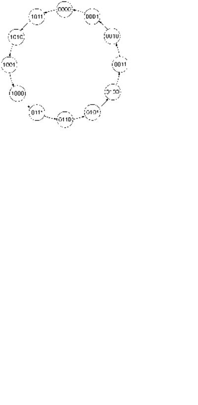
Solution Figure 9.6 shows the state diagram for the mod-12 DOWN counter. The states |
||||||||||||||||||||||||||
|
are identical to those of a mod-12 UP counter, but progress in the opposite direction. Table |
||||||||||||||||||||||||||
|
9.3 shows the count sequence table of this circuit. |
||||||||||||||||||||||||||
FIGURE 9.6
Example 9.2
State Diagram of a Mod-12 DOWN Counter
9.2 • Synchronous Counters |
369 |
Table 9.3 Count-
Sequence Table for a
Mod-12 DOWN Counter
Q3Q2Q1Q0
1011
1010
1001
1000
0111
0110
0101
0100
0011
0010
0001
0000
CLK
Q0
Q1
Q2
Q3
FIGURE 9.7
Example 9.2
Timing Diagram of a Mod-12 DOWN Counter
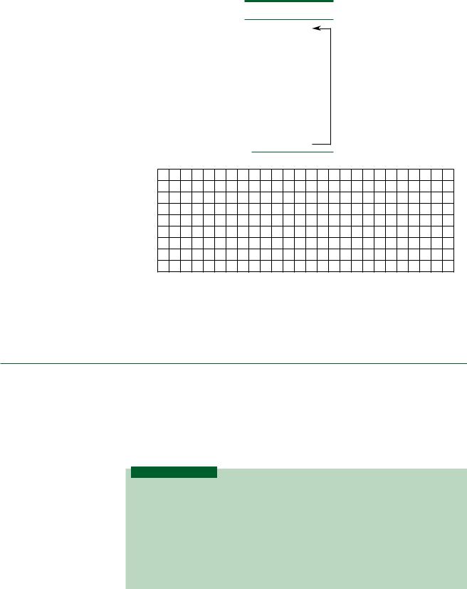
The timing diagram of this counter is illustrated in Figure 9.7. The output starts in state Q3Q2Q1Q0 1011 and counts DOWN until it reaches 0000. On the next pulse, it re-
cycles to 1011 and starts over.
SECTION 9.1 REVIEW PROBLEM
9.1How many outputs does a mod-24 counter require? Is this a full-sequence or a truncated sequence counter? Explain your answer.
9.2Synchronous Counters
K E Y T E R M S
Synchronous counter A counter whose flip-flops are all clocked by the same source and thus change in synchronization with each other.
Present state The current state of flip-flop outputs in a synchronous sequential circuit.
Next state The desired future state of flip-flop outputs in a synchronous sequential circuit after the next clock pulse is applied.
Memory section A set of flip-flops in a synchronous circuit that hold its present state.