

DA 42 NG AFM |
Airplane Description |
|
|
7.10 ELECTRICAL SYSTEM
Doc. No. 7.01.15-E |
Rev. 1 |
18-Feb-2009 |
Page 7 - 49 |
|
|
|
|

Airplane Description |
DA 42 NG AFM |
|
|
7.10.1 GENERAL
The DA 42 NG has 28 Volt DC system, which can be sub-divided into:
-Power generation
-Storage
-Distribution
-Consumers
Power Generation
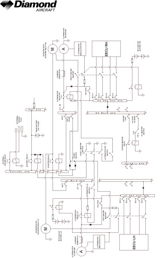
Power generation is provided by two 70 Ampère alternators (generators) which are mounted on the bottom left side of each engine. The alternators are driven by a flat belt.
The power output line of the left hand alternator is connected to the LH MAIN BUS via the LH alternator relay and a 60 Ampère circuit breaker. The power output line of the RH alternator is connected to the RH MAIN BUS via the RH alternator relay and a 60 Ampère circuit breaker. Both main busses are connected to the BATTERY BUS via a 90 Ampère circuit breaker.
Both generator power output lines also run through a current sensor for each alternator, which provides an indication of the power being supplied to the electrical system by an alternator including the current for battery charging on the G1000. In the event of a main battery failure the field of each alternator is energized by two 12 V, 7.2 Ah sealed lead acid batteries (ECU backup battery) connected in series, which are installed under the passengers' seats. The ECU backup batteries provide also electrical power for the ECU for a time of 30 minutes (condition).
The ENGINE MASTER LH (RH) switches connect the ECU backup battery to the alternator field via a 10 Ampère fuse.
Page 7 - 50 |
Rev. 1 |
18-Feb-2009 |
Doc. No. 7.01.15-E |
|
|
|
|
DA 42 NG AFM |
Airplane Description |
|
|
Alternator Control:
Each alternator has an alternator control unit. It measures the alternator output voltage and controls the current through the alternator field coils via a pulse-width modulated signal. To keep the output voltage stable in all load and speed situations, the alternator field signal is modulated accordingly.
The alternator control unit includes a comprehensive set of diagnostic functions that will warn the operator using a caution message (L/R ALTN FAIL) on the G1000 PFD in case of overor undervoltage as well as a couple of other internal warning levels.
Storage
Main battery power is stored in a 24 V, 13.6 Ah lead-acid battery mounted on the right-aft side of the front baggage compartment. The main battery is connected to the HOT BATTERY BUS and to the BATTERY BUS via the 'battery'-relay which is installed in the relay junction box on the center-aft side of the front baggage compartment.
The battery relay is controlled with the ELECT. MASTER switch which is located on the left-hand side of the instrument panel.
In addition, a non-rechargeable dry battery is installed as a further source of power for the backup attitude gyro (artificial horizon) and the flood light. When the EMERGENCY switch is set to ON, these two systems are supplied with power for at least 1.5 hours, independent of all other electrical consumers. During each 100 hour inspection, this battery is checked for proper functioning. Every 2 years or after use (broken seal on the switch) the battery package must be replaced.
Doc. No. 7.01.15-E |
Rev. 1 |
18-Feb-2009 |
Page 7 - 51 |
|
|
|
|

Airplane Description |
DA 42 NG AFM |
|
|
Distribution
Electrical power is distributed via the HOT BATTERY BUS, the BATTERY BUS, the LH
(RH) ECU BUS, the LH (RH) MAIN BUS, and the AVIONIC BUS.
HOT BATTERY BUS:
The HOT BATTERY BUS is directly connected to the main battery and cannot be disconnected from the main battery. The HOT BATTERY BUS provides power to the pilot map/reading light and ELT RCPI unit which are protected by there own fuses.
BATTERY BUS:
The BATTERY BUS is connected to the main battery via the battery relay which can be controlled by the ELECT. MASTER switch. The BATTERY BUS provides power to the
LH (RH) MAIN BUS and heavy duty power to both starters.
ECU BUS:
The LH (RH) ECU BUS is connected to the LH (RH) MAIN BUS via a diode and connected to the power output line of the alternator via diode and a 30 Ampère circuit breaker and provides power for the ECU A and ECU B via the LH (RH) ECU A (B) relays which are controlled by the LH (RH) ENGINE MASTER switch. The LH (RH) ENGINE MASTER switch must be set to ON to connect the ECU A and ECU B to the ECU BUS.
To support the alternator electrical power supply to the ECU’s in case of a malfunction of the main battery, additional sealed-lead-acid batteries (ECU backup battery) are connected to the RH and LH ECU bus.
These batteries are able to provide 30 minutes of engine operation in case of a complete airplane electrical failure. Both engines may stop if the 30 minutes have elapsed.
Page 7 - 52 |
Rev. 1 |
18-Feb-2009 |
Doc. No. 7.01.15-E |
|
|
|
|

DA 42 NG AFM |
Airplane Description |
|
|
MAIN BUS:
The LH (RH) MAIN BUS is connected to the BATTERY BUS via a 90 Ampère circuit breaker. The LH MAIN BUS provides power to the consumers directly connected to the
LH MAIN BUS. The RH MAIN BUS provides power to the consumers directly connected to the RH MAIN BUS and the AVIONIC BUS via the avionics master relay.
The AVIONIC MASTER switch must be set to ON to connect the RH MAIN BUS to the
AVIONIC BUS.
Consumers
The individual consumers (e.g. radio, position lights, etc.) are connected to the appropriate bus via automatic circuit breakers.
Designations and abbreviations used to identify the circuit breakers are explained in Section 1.5 - DEFINITIONS AND ABBREVIATIONS.
Voltmeter
The voltmeter displays the voltage of the electrical system. Under normal operating conditions the alternator voltage is shown, otherwise it displays the main battery voltage.
Ammeter
The ammeter displays the intensity of current which is supplied to the electrical system by the LH (RH) alternator.
Landing and Taxi Lights
Landing and taxi lights are built into the wing center section, and are each operated by means of a switch (LANDING, TAXI) located on the row of switches on the instrument panel.
Doc. No. 7.01.15-E |
Rev. 1 |
18-Feb-2009 |
Page 7 - 53 |
|
|
|
|

Airplane Description |
DA 42 NG AFM |
|
|
Position and Strobe Lights
Combined position and strobe lights (anti collision lights) are installed on both wing tips.
Each system is operated by a switch (POSITION, STROBE) located on the row of switches on the instrument panel.
Flood Light
A two-dimensional light emitter is mounted above the instrument panel. It illuminates the instrument panel as well as all levers, switches, etc. The flood light is switched on and its brightness is adjusted by means of a rotary button (FLOOD) in the LH section of the instrument panel.
Instrument Lighting
With a rotary button (INSTRUMENT) in the LH section of the instrument panel the internal lighting of the instruments is switched on and its brightness is adjusted.
Pitot Heating
The Pitot probe, which provides measurement for the Pitot-static system, is electrically heated. The heating is activated with a switch (PITOT HEAT) located on the row of switches on the instrument panel. The temperature is automatically kept constant by means of a thermal switch on the Pitot probe, and as an additional safety measure a thermal fuse is built in. If this thermal fuse is activated, the Pitot heating can no longer be switched on, and the PITOT FAIL will be displayed. In this case the system should be serviced. The PITOT HT OFF is on if the Pitot heating is switched off.
Page 7 - 54 |
Rev. 1 |
18-Feb-2009 |
Doc. No. 7.01.15-E |
|
|
|
|

DA 42 NG AFM |
Airplane Description |
|
|
External Power Socket
The DA 42 NG has an external 28 Volt DC power socket located on the lower surface of the fuselage nose section. When external power is connected, the control relay is energized and the external power comes online.
The socket itself has three pins:
•a large negative pin
•a large positive pin
•a small positive pin
A diode protects the system from reverse polarity.
Doc. No. 7.01.15-E |
Rev. 1 |
18-Feb-2009 |
Page 7 - 55 |
|
|
|
|