

DA 42 NG AFM |
Airplane Description |
|
|
7.4 INSTRUMENT PANEL
Doc. No. 7.01.15-E |
Rev. 1 |
18-Feb-2009 |
Page 7 - 11 |
|
|
|
|

Airplane Description |
DA 42 NG AFM |
|
|
Major instruments and controls
1 |
Electric master switch |
17 |
Circuit breakers* |
|
|
|
|
2 |
Avionic master switch |
18 |
Backup airspeed indicator |
|
|
|
|
3 |
Engine master switches |
19 |
Backup artificial horizon |
|
|
|
|
4 |
Start switch |
20 |
Backup altimeter |
|
|
|
|
5 |
Pitot-/Stall warning heat switch |
21 |
Emergency compass |
|
|
|
|
6 |
Alternator switches |
22 |
ELT control unit |
|
|
|
|
7 |
ECU test buttons |
23 |
Primary flight display (PFD) |
|
|
|
|
8 |
VOTER switches |
24 |
Audio amplifier / intercom / marker |
|
|
|
beacon receiver |
9 |
Rotary buttons for instrument |
25 |
Multi function display (MFD) |
|
lighting and flood light |
|
|
10 |
Light switches |
26 |
De-ice control panel |
|
|
|
|
11 |
Emergency switch |
27 |
Autopilot control unit (part of MFD) |
|
|
|
|
12 |
Flap selector switch |
28 |
Alt air lever |
|
|
|
|
13 |
Landing gear switch |
29 |
Landing gear emergency |
|
|
|
extension lever |
14 |
Alternate static valve |
30 |
Oxygen pressure indicator |
|
|
|
|
15 |
Microphone socket |
31 |
Oxygen control knob |
|
|
|
|
16 |
Ventilation nozzles |
32 |
Fuel pump switches |
*) Designations and abbreviations used to identify the circuit breakers are explained in Section 1.5 - DEFINITIONS AND ABBREVIATIONS.
NOTE
The figure on previous page shows the typical DA 42 NG installation position for the equipment. The actual installation may vary due to the approved equipment version.
Page 7 - 12 |
Rev. 1 |
18-Feb-2009 |
Doc. No. 7.01.15-E |
|
|
|
|

DA 42 NG AFM |
Airplane Description |
|
|
Cockpit Ventilation
Ventilation in the front is provided by spherical ventilation nozzles (16) in the instrument panel. Furthermore there are spherical nozzles in the roll bar on the left and right side next to the front seats as well as on the central console above the passengers’ heads. The spherical nozzles are opened and closed by twisting.
Doc. No. 7.01.15-E |
Rev. 1 |
18-Feb-2009 |
Page 7 - 13 |
|
|
|
|

Airplane Description |
DA 42 NG AFM |
|
|
7.5 LANDING GEAR
The landing gear is a fully retractable, hydraulically operated, tricycle landing gear. Struts for the landing gear are air oil assemblies.
The hydraulic pressure for the landing gear operation is provided by an electrically powered hydraulic pump, which is activated by a pressure switch, when the required pressure is too low. Electrically actuated hydraulic valves, which are operated with the gear selector switch, provide the required hydraulic pressure for the movement of the landing gear.
The gear selector switch is located on the instrument panel. The switch must be pulled out before it is moved to UP or DOWN position. Gear extension normally takes 6-10 seconds.
When the landing gear is retracted, the main wheels retract inboard into the center wing and the nose wheel retracts forward into the nose section. Hydraulic pressure on the actuators keeps the landing gear in the retracted position. A pressurized gas container acts as an accumulator which keeps the system pressure constant by replacing the volume lost due to the normal actuator leakages. This prevents a permanent starting of the hydraulic pump in flight.
Springs assist the hydraulic system in gear extension and locking the gear in the down position. After the gears are down and the downlock hooks engage, springs maintain force on each hook to keep it locked until it is released by hydraulic pressure.
The three green lights directly next to the landing gear operating switch illuminate to indicate that each gear is in the correct position and locked. If the gear is in neither the full up nor the full down position, a red warning light on the instrument panel illuminates.
Should one power lever be placed in a position below 25% while the landing gear is retracted, a warning horn sounds to alert the pilot that the gear is retracted. Additionally, a CHECK GEAR caution is indicated on the PFD. The same warning appears if the flaps move into position LDG (fully extended) while the gear is retracted.
Page 7 - 14 |
Rev. 1 |
18-Feb-2009 |
Doc. No. 7.01.15-E |
|
|
|
|

DA 42 NG AFM |
Airplane Description |
|
|
To test the gear warning system (refer to 4A.6.1 - PRE-FLIGHT INSPECTION) push the test button close by the gear selector switch. The aural gear alert should appear.
CAUTION
If the aural alert does not appear, an unscheduled maintenance is necessary.
To prevent inadvertent gear retraction on ground, an electric squat switch prevents the hydraulic valve from switching if the master switch is on and the gear extension switch is placed in the UP position.
After take-off, the gear should be retracted before an airspeed of 152 KIAS is exceeded. The landing gear may be extended at any speed up to 188 KIAS.
The landing gear is designed to be manually operated in the event of failure. Since the gear is held in the retracted position by hydraulic pressure, gravity will allow the gear to extend if the system fails for any reason. To extend and lock the gears in the event of failure, it is only necessary to relieve the hydraulic pressure by means of the emergency gear extension lever, which is located under the instrument panel to the left of the center console. Pulling this lever releases the hydraulic pressure and allows the gear to fall free. Before pulling the emergency gear extension lever, place the gear selector switch in the DOWN position.
NOTE
If the emergency gear extension has been pulled due to an emergency, the system has to be checked before pushing the lever in again.
The nose gear is steerable by the use of full rudder pedal travel. A gear damping element, incorporated in the nose gear steering system, prevents shimmy tendencies. When the gear is retracted, the nose wheel centers as it enters the wheel well, and the steering linkage disengages to reduce pedal loads in flight.
Doc. No. 7.01.15-E |
Rev. 1 |
18-Feb-2009 |
Page 7 - 15 |
|
|
|
|
Airplane Description |
DA 42 NG AFM |
|
|
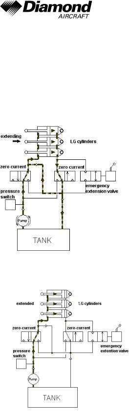
Hydraulic Gear Extension System Schematic
The main landing gear of the DA 42 NG is extended with three hydraulic cylinders. The following schematic figures show the system conditions for each operating mode.
In figure 1 the extension of the landing gear is shown. To reduce the amount of pumped hydraulic fluid during this operation, the return flow is partly led into the feeding flow of the system.
The figure below shows the system status when the landing gear is extended. All hydraulic cylinders are under high pressure.
Page 7 - 16 |
Rev. 1 |
18-Feb-2009 |
Doc. No. 7.01.15-E |
|
|
|
|
DA 42 NG AFM |
Airplane Description |
|
|
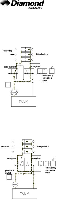
The operating mode for the retraction of the landing gear is shown in the next figure. While energizing the right hydraulic valve, the fluid flow in the hydraulic system is started due to different piston areas of the landing gear cylinders although the pressure on both sides of the system is equal.
While the landing gear is retracted both valves are energized and excessive hydraulic fluid on one side is drained into the tank. This configuration of the system is shown in the following figure.
Doc. No. 7.01.15-E |
Rev. 1 |
18-Feb-2009 |
Page 7 - 17 |
|
|
|
|
Airplane Description |
DA 42 NG AFM |
|
|
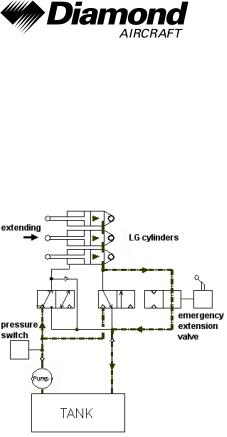
For an emergency extension of the landing gear, the hydraulic fluid can pass through an emergency extension valve so that the gear is extended by gravity. The condition of the system is shown in the figure below.
Page 7 - 18 |
Rev. 1 |
18-Feb-2009 |
Doc. No. 7.01.15-E |
|
|
|
|
DA 42 NG AFM |
Airplane Description |
|
|
Wheel Brakes
Hydraulically operated disk brakes act on the wheels of the main landing gear. The wheel brakes are individually operated by means of toe pedals.
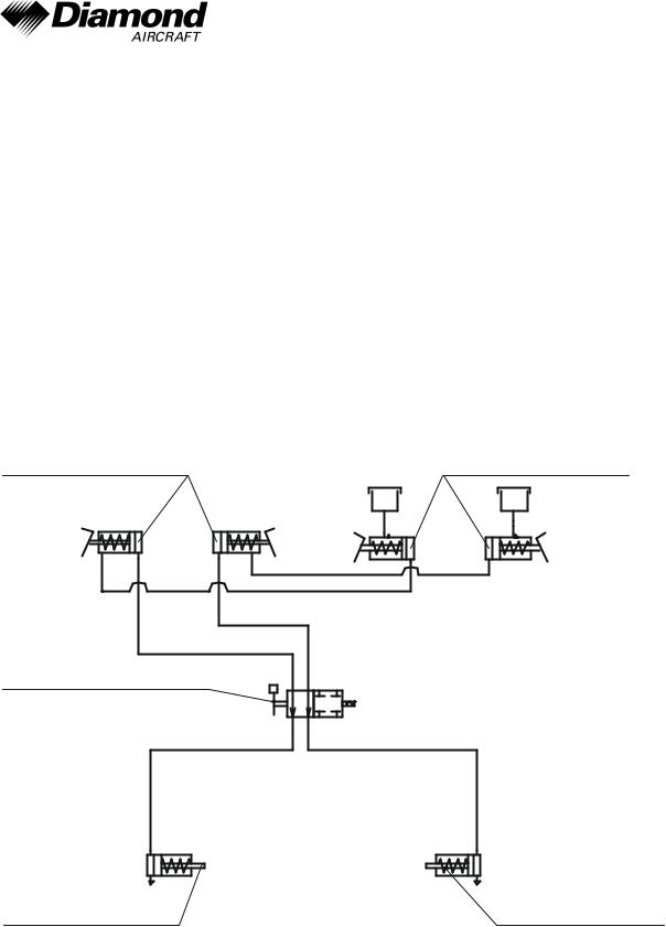
Parking Brake
The lever is located on the small center console under the instrument panel and is in the upper position when the brakes are released. To operate the parking brake, pull the lever downwards until it catches. Brake pressure is built up by multiple operation of the toe brake pedals, and is maintained until the parking brake is released. To release, the lever is pushed upwards.
brake pedals, |
brake pedals, |
pilot |
co-pilot |
parking brake valve
brake cylinder, LH |
brake cylinder, RH |
Doc. No. 7.01.15-E |
Rev. 1 |
18-Feb-2009 |
Page 7 - 19 |
|
|
|
|