

- •Section 1: System Overview
- •1.1 PFD/MFD Controls
- •1.2 PFD Softkeys
- •1.3 MFD Softkeys
- •1.4 MFD Page Groups
- •1.5 Vertical Navigation
- •1.6 Backlighting
- •1.7 Database Updates
- •Jeppesen Aviation Database
- •Garmin Databases
- •Section 2: Flight Instruments
- •2.1 Airspeed Indicator
- •Speed Indication
- •Speed Ranges
- •Airspeed Trend Vector
- •Vspeed References
- •2.2 Attitude Indicator
- •2.3 Altimeter
- •Selected Altitude Bug
- •Altitude Trend Vector
- •Barometric Setting Box
- •Altitude Alerting
- •Metric Display
- •Low Altitude Annunciation
- •2.5 Marker Beacon Annunciations
- •2.6 Vertical Speed Indicator
- •2.7 Barometric Altitude Minimums
- •2.8 Horizontal Situation Indicator (HSI)
- •Course Pointer
- •Course Deviation Indicator (CDI)
- •Bearing Pointers and Information Windows
- •DME (optional)
- •Navigation Source
- •2.9 Wind Data
- •2.10 Generic Timer
- •3.1 Engine Display
- •3.2 Lean Display
- •Normally-aspirated Aircraft
- •Turbocharged Aircraft
- •3.3 System Display
- •4.1 Radio Status Indications
- •4.2 Volume
- •4.3 Automatic Squelch
- •4.4 Quickly Activating 121.500 MHz
- •4.5 Optional NAV Radios
- •DME Radio (optional)
- •ADF Radio (optional)
- •Auto-tuning on the PFD
- •Auto-tuning on the MFD
- •4.7 Transponder
- •Mode Selection
- •Reply Status
- •Code Selection
- •Flight ID Reporting
- •Section 5: Audio Panel
- •5.1 COM Radio Selection
- •5.2 Cabin Speaker
- •5.3 Passenger Address (PA) System (T)182T and (T)206H Only
- •5.4 Marker Beacon Receiver
- •Marker Beacon Signal Sensitivity
- •5.5 Nav Radio Audio Selection
- •5.6 Intercom System (ICS) Isolation
- •5.7 Intercom Squelch Control
- •5.8 Digital Clearance Recorder and Player
- •6.1 AFCS Controls
- •6.2 Flight Director Operation
- •Activating the Flight Director
- •Command Bars
- •AFCS Status Box
- •6.3 Flight Director Modes
- •Pitch Modes
- •Roll Modes
- •6.4 Autopilot Operation
- •Flight Control
- •Engaging the Autopilot
- •Control Wheel Steering
- •Disengaging the Autopilot
- •6.5 Example Procedures
- •Departure
- •Intercepting a VOR Radial
- •Flying a Flight Plan/GPS Course
- •Descent
- •Approach
- •Go Around/Missed Approach
- •6.6 AFCS Annunciations and Alerts
- •AFCS Status Alerts
- •Overspeed Protection
- •Section 7: Navigation
- •7.1 Navigation Map Page
- •Direct-to Navigation from the MFD
- •Direct-to Navigation from the PFD
- •7.3 Navigating an Example Flight Plan
- •7.4 Airport Information
- •7.5 Intersection Information
- •7.6 NDB Information
- •7.7 VOR Information
- •7.9 Nearest Airports
- •Nearest Airport Information on the MFD
- •Nearest Airports Information on the PFD
- •7.10 Nearest Intersections
- •7.11 Nearest NDB
- •7.12 Nearest VOR
- •7.13 Nearest User Waypoint
- •7.14 Nearest Frequencies
- •7.15 Nearest Airspaces
- •Section 8: Flight Planning
- •8.1 User Defined Waypoints
- •Select the User WPT Information Page
- •Create User Waypoints from the Navigation Map Page
- •8.2 Viewing the Active Flight Plan
- •8.3 Activate a Stored Flight Plan
- •8.4 Activate a Flight Plan Leg
- •8.5 Stop Navigating a Flight Plan
- •8.6 Invert Active Flight Plan
- •8.7 Create a New Flight Plan
- •Create a New Flight Plan Using the MFD
- •Create a New Flight Plan Using the PFD
- •8.8 Enter an Airway in a Flight Plan
- •8.9 Load a Departure
- •8.10 Load an Arrival
- •8.11 Load an Approach
- •8.12 Remove a Departure, Arrival, Approach, or Airway from a Flight Plan
- •8.13 Store a Flight Plan
- •8.14 Edit a Stored Flight Plan
- •8.15 Delete a Waypoint from the Flight Plan
- •8.16 Invert and Activate a Stored Flight Plan
- •8.17 Copy a Flight Plan
- •8.18 Delete a Flight Plan
- •8.19 Graphical Flight Plan Creation
- •8.20 Trip Planning
- •Section 9: Procedures
- •9.1 Arrivals and Departures
- •Load and Activate a Departure Procedure
- •Load and Activate An Arrival Procedure
- •9.2 Approaches
- •Load and/or Activate an Approach Procedure
- •Activate An Approach in the Active Flight Plan
- •Section 10: Hazard Avoidance
- •10.1 Customizing the Hazard Displays on the Navigation Map
- •10.2 STORMSCOPE® (Optional)
- •Displaying Stormscope Lightning Data on the Navigation Map Page
- •Stormscope Page
- •10.3 XM Weather (Service Optional)
- •Displaying METAR and TAF information on the Airport Information Page
- •Displaying Weather on the Weather Data Link Page
- •Weather Products & Symbols
- •Weather Product Age
- •10.4 Traffic Systems
- •Traffic Information Service (TIS)
- •Traffic Advisory System (TAS) (Optional)
- •ADS-B Traffic (Optional)
- •10.5 Terrain and Obstacle Proximity
- •Displaying Terrain and Obstacles on the Navigation Map
- •10.6 TERRAIN-SVS Display (Optional)
- •Displaying Terrain on the TERRAIN-SVS Page
- •Enable/Disable Aviation Data
- •TERRAIN-SVS Alerts
- •Terrain Inhibit
- •Forward Looking Terrain Avoidance (FLTA)
- •10.7 Terrain Awareness & Warning System (TAWS) Display (Optional)
- •Displaying Terrain on the TAWS Page
- •Enable/Disable Aviation Data
- •TAWS Inhibit
- •Manual System Test
- •Forward Looking Terrain Avoidance (FLTA)
- •Premature Descent Alert (PDA)
- •Excessive Descent Rate Alert (EDR)
- •“Five-Hundred” Aural Alert
- •Displaying Terrain and Obstacles on the Navigation Map
- •Pop-up Alerts
- •TAWS Alerts Summary
- •Alert Annunciations
- •11.1 Synthetic Vision System (SVS) (Optional)
- •SVS Operation
- •SVS Features
- •Field of View
- •11.2 SafeTaxi
- •11.3 ChartView
- •Chart Options
- •Day/Night View
- •11.4 FliteCharts
- •Chart Options
- •Day/Night View
- •11.5 XM Radio Entertainment
- •Using XM Radio
- •Automatic Audio Muting
- •11.6 Scheduler
- •11.7 Electronic Checklists
- •12.1 Reversionary Mode
- •12.2 Abnormal COM Operation
- •12.3 Unusual Attitudes
- •12.4 Stormscope Operation with loss of Heading Input
- •12.5 Hazard Displays with Loss of GPS Position
- •12.6 Dead Reckoning
- •13.1 Alert Level Definitions
- •13.2 NAV III Aircraft Alerts
- •CAUTION Alerts (T182, T206, and 206 with Prop De-Ice Only)
- •Safe Operating Annunciation (T182, T206, and 206 with Prop De-Ice Only)
- •13.3 CO Guardian Messages
- •13.4 AFCS Alerts
- •System Status Annunciation
- •13.5 TAWS Alerts
- •13.6 Other G1000 Aural Alerts
- •13.7 G1000 System Annunciations
- •13.8 G1000 System Message Advisories
- •MFD & PFD Message Advisories
- •Database Message Advisories
- •GMA 1347 Message Advisories
- •GIA 63 Message Advisories
- •GIA 63W Message Advisories
- •GEA 71 Message Advisories
- •GTX 33 Message Advisories
- •GRS 77 Message Advisories
- •GMU 44 Message Advisories
- •GDL 69/69A Message Advisories
- •GDC 74A Message Advisories
- •Miscellaneous Message Advisories
- •Index
- •1.1 PFD/MFD Controls
- •Speed Ranges
- •3.1 Engine Display
- •4.7 Transponder
- •Command Bars
- •Flight Control
- •Control Wheel Steering
- •Select the MAP Page Group
- •Select the Airport Information Page
- •Select the Intersection Information Page
- •Select the NDB Information Page
- •Select the VOR Information Page
- •Select the Nearest Intersections Page
- •Select the Nearest NDB Page
- •Select the Nearest VOR Page
- •Select the Nearest User Waypoint Page
- •Select the Nearest Frequencies Page
- •Select the Nearest Airspaces Page
- •11.4 FliteCharts
- •System Status Annunciation
Section 12: Abnormal
Operation
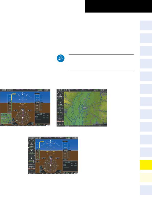
12.1 Reversionary Mode
Should a system detected failure occur in either display, the G1000 automatically enters Reversionary Mode. In Reversionary Mode, critical flight instrumentation is combined with engine instrumentation on the remaining display. Reduced navigation capability is available on the Reversionary Mode display.
Normal PFD Display
SECTION 12 – ABNORMAL
OPERATION
Reversionary display mode can also be manually activated by the pilot if the system fails to detect a display problem. The Reversionary Mode is activated manually by pressing the red Display Backup Button on the bottom of the audio panel (GMA 1347). Pressing the red Display Backup Button again deactivates Reversionary Mode.
NOTE: The Cessna Pilot’s Operating Handbook (POH) always takes precedence over the information found in this section.
Normal MFD Display
MFD in Reversionary Mode
Figure 12-1 G1000 Reversionary Mode: Failed PFD
190-00384-09 Rev. A |
Garmin G1000 Cockpit Reference Guide for the Cessna Nav III |
12-1 |
SECTION 12 – ABNORMAL
OPERATION
12.2 Abnormal COM Operation
When a COM tuning failure is detected by the system, the emergency frequency (121.500 MHz) is automatically loaded into the active frequency field of the COM radio for which the tuning failure was detected. In the event of a dual display failure, the emergency frequency (121.500 MHz) automatically becomes the active frequency to the pilot through the pilot headset.
12.3 Unusual Attitudes
The PFD ‘declutters’ when the aircraft enters an unusual attitude. Only the primary functions are displayed in these situations.
The following information is removed from the PFD (and corresponding softkeys are disabled) when the aircraft experiences unusual attitudes:
|
• |
Traffic Annunciations |
• |
Windows displayed in |
|
• |
AFCS Annunciations |
|
the lower right corner |
|
• |
Flight Director |
|
of the PFD: |
|
|
Command Bars |
– |
Timer/References |
|
• |
Inset Map |
– |
Nearest Airports |
|
• |
Temperatures |
– |
Flight Plan |
|
• |
DME Information |
– |
Messages |
|
|
Window |
– |
Procedures |
|
• |
Wind Data |
– |
DME Tuning |
|
• |
Selected Heading Box |
• |
Barometric Minimum |
|
• |
Selected Course Box |
|
Descent Altitude Box |
|
• |
Transponder Status |
• |
Glideslope, Glidepath, |
|
|
Box |
|
and Vertical Deviation |
|
|
|
||
|
• |
System Time |
|
Indicators |
|
• |
PFD Setup Menu |
• |
Altimeter Barometric |
|
|
|
|
Setting |
|
|
|
• |
Selected Altitude |
|
|
|
• |
VNV Target Altitude |
|
|
|
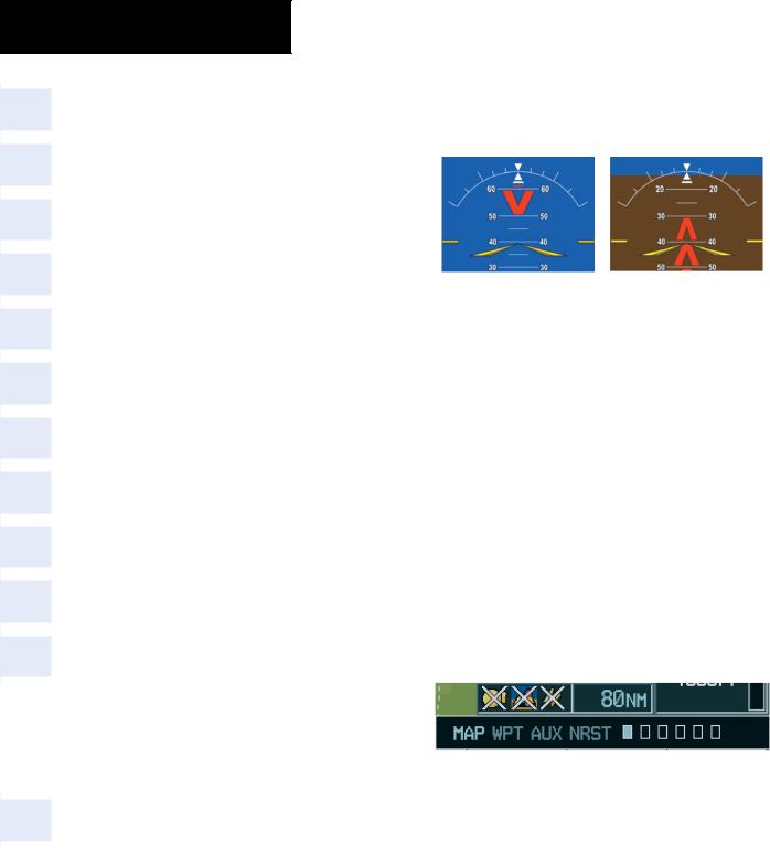
Red extreme pitch warning chevrons pointing toward the horizon are displayed starting at 50 degrees above and 30 degrees below the horizon line.
Figure 12-2 Extreme Pitch Indication
12.4Stormscope Operation with loss of Heading Input
If heading is lost, strikes and/or cells must be cleared manually after the execution of each turn. This is to ensure that the strike and/or cell positions are depicted accurately in relation to the nose of the aircraft.
12.5Hazard Displays with Loss of GPS Position
If GPS position is lost, or becomes invalid, selected hazards being displayed on the Navigation Map Page are removed until GPS position is again established. The icons in the lower right of the screen, indicating the selected functions for display, will show an ‘X’, as shown in Figure 12-3.
Figure 12-3 Loss of Hazard Functions with Loss of GPS Position
12-2 |
Garmin G1000 Cockpit Reference Guide for the Cessna Nav III |
190-00384-09 Rev. A |
12.6 Dead Reckoning
WARNING: DR Mode is inherently less accurate than the standard GPS/WAAS Mode due to the lack of satellite measurements needed to determine a position. Changes in wind speed and/or wind direction compound the relative inaccuracy of DR Mode. Because of this degraded accuracy, the crew must maintain position awareness using other navigation equipment until GPS-derived position data is restored.
While in Enroute or Oceanic phase of flight, if the G1000 detects an invalid GPS solution or is unable to calculate a GPS position, the system automatically reverts to Dead Reckoning (DR) Mode. In DR Mode, the G1000 uses its last-known position combined with continuously updated airspeed and heading data (when available) to calculate and display the aircraft’s current estimated position.
NOTE: Dead Reckoning Mode only functions in Enroute (ENR) or Oceanic (OCN) phase of flight. In all other phases, an invalid GPS solution produces a ‘NO GPS POSITION’ annunciation on the map and the G1000 stops navigating in GPS Mode.
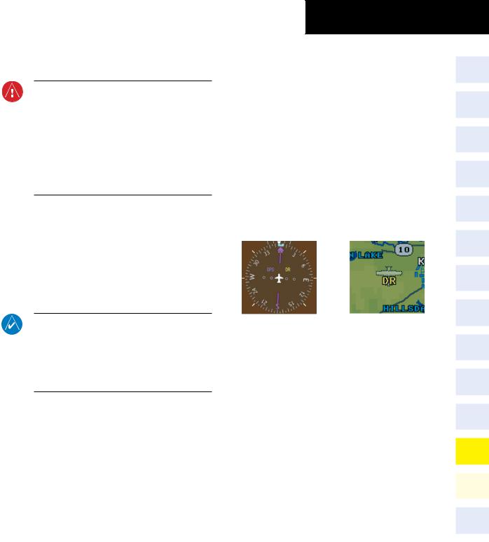
DR Mode is indicated on the G1000 by the appearance of the letters ‘DR’ superimposed in yellow over the ‘own aircraft’ symbol as shown in Figure 12-4. In addition, ‘DR’ is prominently displayed, also in yellow, on the HSI slightly above and to the right of the aircraft symbol on the CDI as shown in Figure 12-4. Also, the CDI deviation bar is removed from the display. Lastly, but at the same time, a ‘GPS NAV LOST’ alert message appears on the PFD.
SECTION 12 – ABNORMAL
OPERATION
Normal navigation using GPS/WAAS source data resumes automatically once a valid GPS solution is restored.
It is important to note that estimated navigation data supplied by the G1000 in DR Mode may become increasingly unreliable and must not be used as a sole means of navigation. If while in DR Mode airspeed and/or heading data is also lost or not available, the DR function may not be capable of accurately tracking your estimated position and, consequently, the system may display a path that is different than the actual movement of the aircraft. Estimated position information displayed by the G1000 through DR while there is no heading and/or airspeed data available should not be used for navigation.
CDI ‘DR’ Indication on PFD Symbolic Aircraft (Map pages and Inset Map)
Figure 12-4 Dead Reckoning Indications
As a result of operating in DR Mode, all GPS-derived data is computed based upon an estimated position and is displayed as yellow text on the display to denote degraded navigation source information. This data includes the following:
•NavigationStatusBoxfieldsexceptActiveLeg,TAS, and DTK
•GPS Bearing Pointer
•Wind data and pointers in the Wind Data Box on the PFD and MFD
•Current Track Indicator
•All Bearing Pointer Distances
•Active Flight Plan distances, bearings, and ETE values
190-00384-09 Rev. A |
Garmin G1000 Cockpit Reference Guide for the Cessna Nav III |
12-3 |

SECTION 12 – ABNORMAL
OPERATION
Also, while the G1000 is in DR Mode, the autopilot will not couple to GPS, and Terrain Proximity, TERRAIN-SVS, and TAWS are disabled. Additionally, the accuracy of all nearest information (airports, airspaces, and waypoints) is questionable. Finally, airspace alerts continue to function, but with degraded accuracy.
|
Garmin G1000 Cockpit Reference Guide for the Cessna Nav III |
190-00384-09 Rev. A |
|
||
12-4 |
Section 13: Annunciations &
Alerts
Note: The Cessna aircraft Pilot’s Operating Handbook (POH) supersedes information found in this document.
The G1000 Alerting System conveys alerts to the pilot using a combination of the following items:
•Annunciation Window: The Annunciation Window displays abbreviated annunciation text. Text color is based on alert levels described later in the Alert Levels Definitions section. The Annunciation Window is located to the right of the Altimeter and Vertical Speed Indicator on the display. All Cessna Nav III annunciations can be displayed simultaneously in the Annunciation Window. A white horizontal line separates annunciations that are acknowledged from annunciations that are not yet acknowledged. Higher priority annunciations are displayed towards the top of the window. Lower priority annunciations are displayed towards the bottom of the window.
•Alerts Window: The Alerts Window displays alert text messages. Up to 64 prioritized alert messages can be displayed in the Alerts Window. Pressing the ALERTS Softkey displays the Alerts Window. Pressing the ALERTS Softkey a second time removes the Alerts Window from the display. When the Alerts Window is displayed, the pilot can use the large FMS Knob to scroll through the alert message list.
SECTION 13 – ANNUNCIATIONS
& ALERTS
•Softkey Annunciation: During certain alerts, the ALERTS Softkey may appear as a flashing annunciation to accompany an alert. The ALERTS Softkey assumes a new label consistent with the alert level (WARNING, CAUTION, or ADVISORY). By pressing the softkey annunciation, the pilot acknowledges awareness of the alert. The softkey then returns to the previous ALERTS label. If alerts are still present, the ALERTS label is displayed in inverse video (white background with black text). The pilot can press the ALERTS Softkey a second time to view alert text messages.
•System Annunciations: Typically, a large red ‘X’ appears in windows when a failure is detected in the LRU providing the information to the window. See the G1000 System Annunciations section for more information.
•Audio Alerting System: The G1000 system issues audio alert tones when specific system conditions are met. See the Alert Levels Definitions section for more information.
System
Annunciation
Red ‘X’
Annunciation
Window
Alerts Window
ALERTS Softkey
Annunciation
|
Figure 13-1 G1000 Alerting System |
|
190-00384-09 Rev. A |
Garmin G1000 Cockpit Reference Guide for the Cessna Nav III |
13-1 |