

4)Turn the large FMS Knob to select the desired airport.
5)Press the ENT Key. The cursor is now displayed on ‘ACTIVATE?’.
6)Press the ENT Key again to activate a Direct-to.
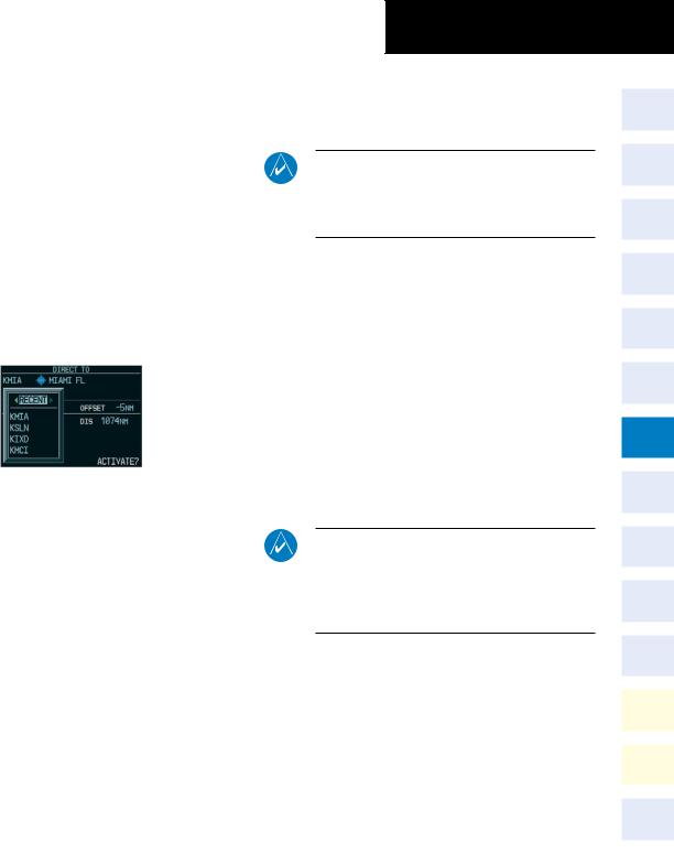
Select a Direct-to Destination to a Recently Entered Identifier
1)Press the Direct-to ( ) Key.
2)Turn the small FMS Knob to the left. Initially, a flight plan waypoint list is displayed as in Figure 7-8. The list is only populated when navigating a flight plan.
Figure 7-10 Recently Entered Waypoints List (PFD)
3)Turn the small FMS Knob to the right to display the ‘RECENT’ waypoints as shown in Figure 7-10.
4)Turn the large FMS Knob to select the desired airport.
5)Press the ENT Key. The cursor is now displayed on ‘ACTIVATE?’.
6)Press the ENT Key again to activate a Direct-to.
Cancelling Direct-to Navigation
1)Press the Direct-to ( ) Key.
2)Press the MENU Key to display the Options Window. The cursor flashes on ‘Cancel Direct-to NAV’.
3)Press the ENT Key to cancel the direct-to.
SECTION 7 – NAVIGATION
7.3Navigating an Example Flight Plan
NOTE: The following example flight plan is for instructional purposes only. All database information depicted should be considered not current.
The following discussion is an example of navigating a flight plan with the WAAS capable GPS system while the G1000 provides vertical guidance through descents. A lateral flight plan (LNAV) would be navigated in much the same way, but would not include vertical guidance when the final approach course is active.
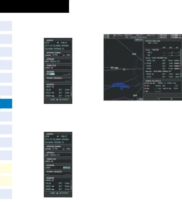
The example is a flight plan from KMKC to KCOS filed using the TIFTO2 departure, various Victor Airways, and the DBRY1 arrival with the transition at TBE. Enroute altitude will be 12,000 feet. An LPV (WAAS) approach will be selected for runway 35R. A missed approach will be executed at the Missed Approach Point (MAP). A few enroute changes are demonstrated.
NOTE: If the loaded arrival procedure has published altitudes contained in the navigation database, these are for turbojet aircraft only. Accept or change these values as desired to meet the requirements of the clearance.
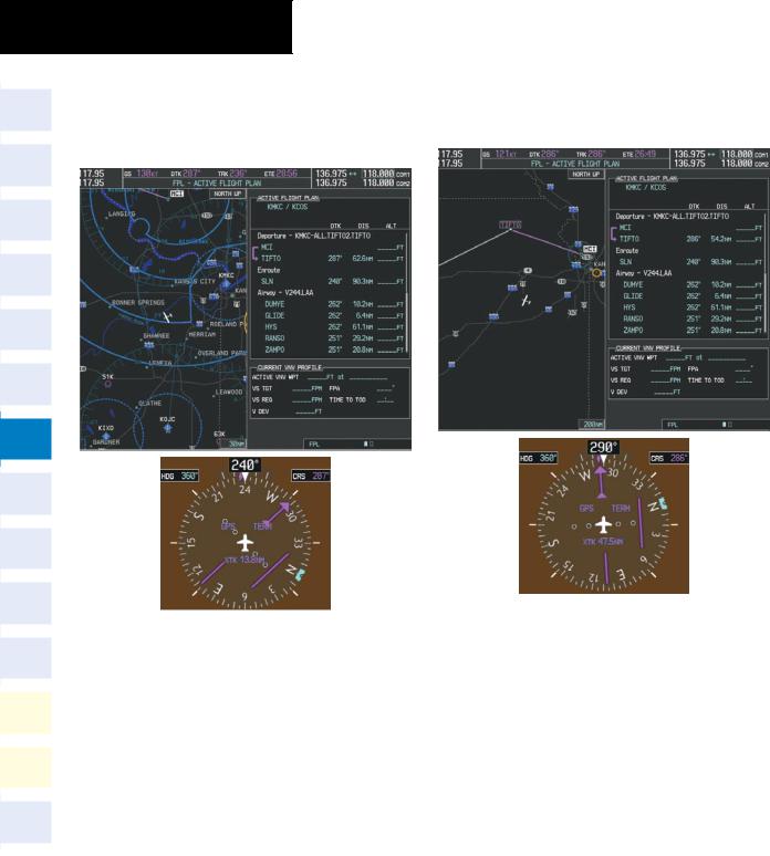
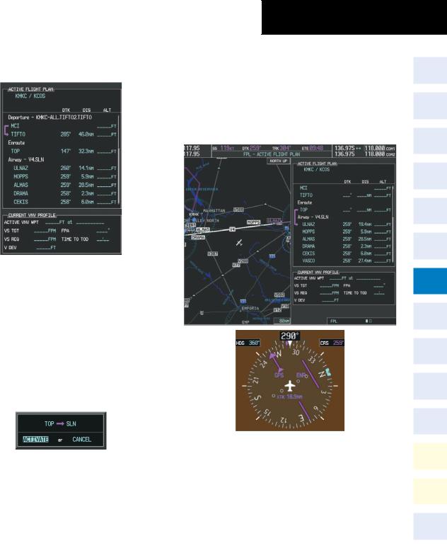
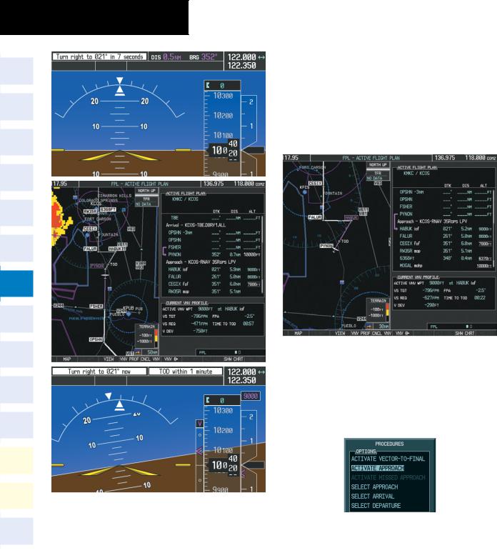
1)Prior to departure, the TIFTO2 departure, the airways, and the DBRY1 arrival at KCOS are loaded. See the Procedures section for loading departures and arrivals. Note the magenta arrow in Figure 7-11 indicating the active departure leg.
After takeoff, ATC assigns a heading of 240º.
190-00384-09 Rev. A |
Garmin G1000 Cockpit Reference Guide for the Cessna Nav III |
7-5 |
SECTION 7 – NAVIGATION
2)Figure 7-11 shows the aircraft on the assigned heading of 240º. ‘TERM’ (Terminal) is the current CDI flight phase displayed on the HSI indicating 1.0 nm CDI scaling.
3)ATC now assigns routing to join V4. A heading of 290º is assigned to intercept V4. The aircraft turns to heading 290° as seen in Figure 7-12.
Figure 7-12 Assigned Heading of 290º
Figure 7-11 Assigned Heading of 240º
7-6 |
Garmin G1000 Cockpit Reference Guide for the Cessna Nav III |
190-00384-09 Rev. A |
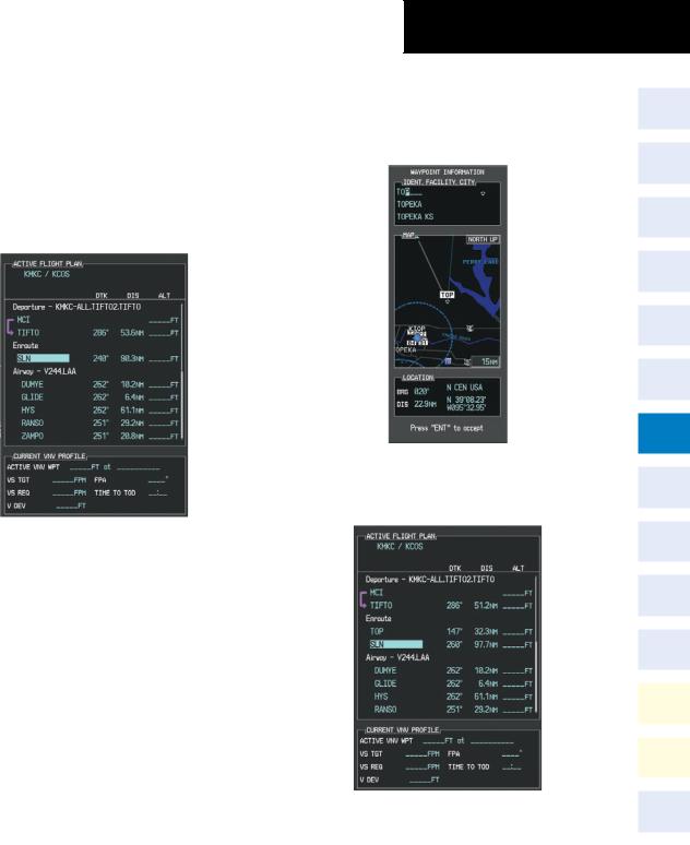
4)V4 is now entered into the flight plan.
a)Press the FMS Knob to activate the cursor.
b)The desired entry point for V4 (TOP) must now be entered. Turn the large FMS Knob to highlight the desired flight plan insertion point as shown in Figure 7-13. The V4 entry point (TOP) is placed immediately above the highlighted waypoint (SLN).
SECTION 7 – NAVIGATION
c)Turn the small FMS Knob to display the Waypoint Information Window. Enter the desired beginning point for V4 leg, in this example, Topeka VOR (TOP) is used as shown in Figure 7-14.
Figure 7-14 Entering V4 Entry Point
d) Press the ENT Key. TOP is now inserted into the flight plan as in Figure 7-15.
Figure 7-13 Begin Adding V4 to the Flight Plan
|
Figure 7-15 TOP Inserted into the Flight Plan |
|
190-00384-09 Rev. A |
Garmin G1000 Cockpit Reference Guide for the Cessna Nav III |
7-7 |
SECTION 7 – NAVIGATION
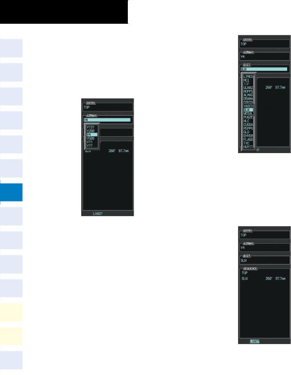
e)With SLN still highlighted as in Figure 7-15, turn the small FMS Knob to the right. The Waypoint Information Page is displayed and the LD AIRWY Softkey is now available.
f)Press the LD AIRWY Softkey to display the list of available airways for TOP as seen in Figure 7-16.
Figure 7-16 List of Available Airways for TOP
g)Turn either FMS Knob to highlight V4 in the list as seen in Figure 7-16.
h)Press the ENT Key. The list of V4 airway exit points is now displayed as in Figure 7-17.
Figure 7-17 List of Available Exits for V4
i)If necessary, turn either FMS Knob to select the desired exit. In this case Salina VOR (SLN) is selected as seen in Figure 7-17.
j)Press the ENT Key. The selected airway and exit are displayed the prompt “LOAD?” highlighted as in Figure 7-18.
Figure 7-18 Ready to Load V4
k) Press the ENT Key.
7-8 |
Garmin G1000 Cockpit Reference Guide for the Cessna Nav III |
190-00384-09 Rev. A |
l)V4 is now loaded into the flight plan as shown in Figure 7-19.
SECTION 7 – NAVIGATION
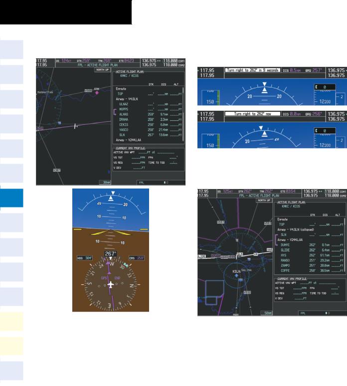
(XTK) distance on the HSI indicating 16.9 nm to the intercept point. Note the phase of flight remained in Terminal (TERM) mode up to this point because a departure leg was active. Since a leg after the departure is now active, the current CDI flight phase is ENR (Enroute) and CDI scaling has changed to 2.0 nm.
Figure 7-19 V4 is Loaded in the Flight Plan
5)V4 is now made the active leg of the flight plan.
a)Press the FMS Knob to activate the cursor.
b)Turn the large FMS Knob to highlight SLN. The TO waypoint of the leg is selected in order to activate the leg.
c)Press the ACT LEG Softkey. The confirmation window is now displayed as in Figure 7-20. Note the TOP to SLN leg is actually part of V4.
Figure 7-20 Comfirm Active Leg
d)Verify the displayed leg is the desired leg and press the ENT Key. Note in Figure 7-21, the magenta arrow in the flight plan window and magenta line on the map indicating V4 is now the active flight plan leg. Note also, the crosstrack
Figure 7-21 V4 Now Active Leg
6)The aircraft continues on heading 290º. When the crosstrack distance is less than 2.0 nm, the XTK disappears from the HSI and the CDI is positioned on the last dot indicating a 2.0 nm distance from the centerline of the next course.
190-00384-09 Rev. A |
Garmin G1000 Cockpit Reference Guide for the Cessna Nav III |
7-9 |
SECTION 7 – NAVIGATION
7)As the CDI approaches center, the aircraft turns onto the active leg as seen in Figure 7-22.
8)At SLN, Victor Airway 244 (V244) is intercepted. Turn prompts are displayed in the PFD Navigation Status Box as seen in Figure 7-23.
Figure 7-23 Turn to Intercept V244
9)As seen in Figure 7-24,V244 is now the active flight plan leg.
Figure 7-24 V244 Now Active Leg
Figure 7-22 Turn on to Active Leg
7-10 |
Garmin G1000 Cockpit Reference Guide for the Cessna Nav III |
190-00384-09 Rev. A |
SECTION 7 – NAVIGATION
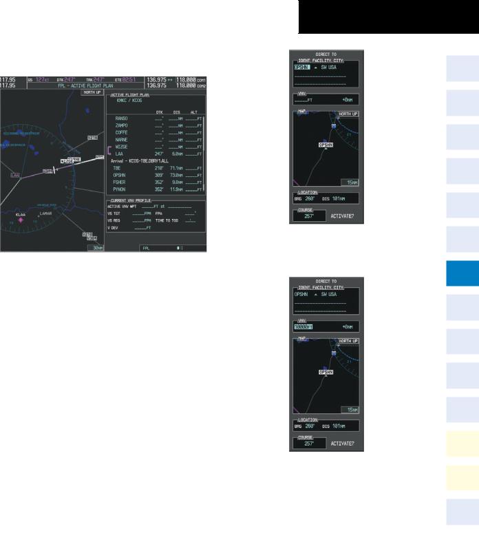
10)At Lamar VOR (LAA) V263 is intercepted. See Figure 7-25.
Figure 7-25 HYS to LAA Leg Active
11)ATC grants clearance to proceed direct to OPSHN intersection to begin the arrival procedure and issues a crossing altitude restriction of 10,000 feet at OPSHN.
a)Press the FMS Knob to activate the cursor.
b)Turn the large FMS Knob to select OPSHN in the flight plan list.
c)Press the Direct-to ( ) Key. The Direct-to Window is now displayed as shown in Figure 7-26.
Figure 7-26 Direct To OPSHN
d)Turn the large FMS Knob to place the cursor in the VNV altitude field as shown in Figure 7-27.
Figure 7-27 Enter VNV Altitude
e)An altitude of 10,000 feet is entered as requested by ATC.
190-00384-09 Rev. A |
Garmin G1000 Cockpit Reference Guide for the Cessna Nav III |
7-11 |
SECTION 7 – NAVIGATION
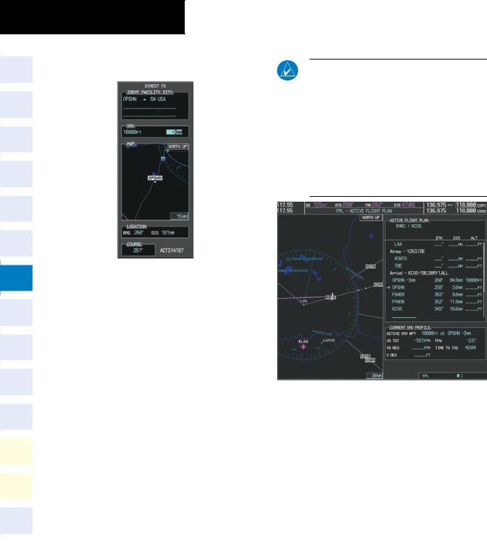
f)Press the ENT Key. The cursor is now displayed in the VNV offset field as shown in Figure 7-28.
NOTE: If the loaded arrival procedure has waypoints with altitude constraints retrieved from the database, those altitudes are displayed as white numerals. This indicates the altitudes will not be used by the system for vertical guidance until manually accepted by the pilot. To accept the displayed altitude, place the cursor over the altitude and press the ENT Key. The altitude entry then changes to light blue numerals, indicating the altitude will now be used by the system for providing vertical guidance.
Figure 7-28 Enter VNV Offset Distance
g)Enter the offset, or distance from the waypoint at which the selected altitude will be reached. In this case, three miles prior to OPSHN is entered. In other words, the G1000 gives vertical guidance so the aircraft will arrive at an altitude of 10,000 feet three miles prior to OPSHN.
h)Press the ENT Key twice to activate the direct-to. Note, in Figure 7-29, the magenta arrow in the Active Flight Plan Window indicating the direct-to OPSHN after the offset waypoint for OPSHN. The preceding offset waypoint indicates the offset distance and altitude that was previously entered. The remaining waypoints in the loaded arrival procedure have no database specified altitudes, therefore, dashes are displayed. Keep the CDI centered and maintain a track along the magenta line to OPSHN.
Note the Direct-to waypoint is within the loaded arrival procedure, therefore, phase of flight scaling for the CDI changes to Terminal Mode and is annunciated by displaying ‘TERM’ on the HSI.
Figure 7-29 Direct-to Active
12)The aircraft is proceeding to OPSHN. The expected approach is the RNAV LPV approach to runway 35R, so it is selected.
a)Press the PROC Key to display the Procedures Window.
If the GPS system is not WAAS capable, or WAAS is not available, the LPV approach will not be displayed in the list of available approaches. Selecting the LNAV approach for runway 35R gives vertical guidance up to the IAF.
7-12 |
Garmin G1000 Cockpit Reference Guide for the Cessna Nav III |
190-00384-09 Rev. A |
b)‘SELECT APPROACH’ should be highlighted as shown in Figure 7-30.
SECTION 7 – NAVIGATION
d)Turn either FMS Knob to select the LPV approach for 35R as shown in Figure 7-31.
e)Press the ENT Key. A list of available transitions for the selected approach is displayed as shown on Figure 7-32.
Figure 7-30 Procedures Window
c)Press the ENT Key. A list of available approaches for the destination airport is displayed as in Figure 7-31.
Figure 7-31 List of Available Approaches
Figure 7-32 List of Available Transitions
f)Turn either FMS Knob to select the desired transition. In this case, the Initial Approach Fix (IAF) at HABUK is used.
g)Press the ENT Key.
190-00384-09 Rev. A |
Garmin G1000 Cockpit Reference Guide for the Cessna Nav III |
7-13 |
SECTION 7 – NAVIGATION
h)Turn the small FMS Knob in the direction of the green arrow to select BARO as shown in Figure 7-33. This enables the barometric minimums bug display on the altimeter.
j)With ‘LOAD?’ highlighted, again press the ENT Key. The selected approach is added to the flight plan as seen in Figure 7-35.
Figure 7-33 Barometric Minimums Enabled
i)Press the ENT Key. Turn the small FMS Knob to enter the published decision altitude for the approach procedure. The altitude is entered to the nearest 10 feet. Press the ENT Key.
Figure 7-34 Decision Altitude Entered
Figure 7-35 Loaded Approach
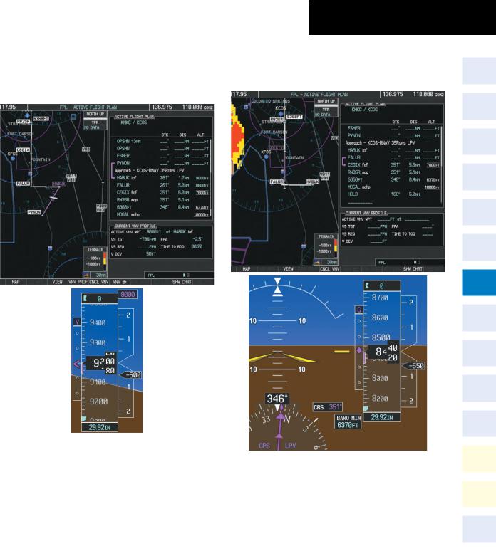
13)Note the altitude constraints associated with each of the approach waypoints as seen in Figure 7-36. These altitudes are loaded from the database and are displayed as light blue text, indicating these values are “designated” for use in computing vertical deviation guidance.
If it is desirable not to use the displayed altitude for calculating vertical deviation guidance, perform the following:
a)Press the FMS Knob to activate the cursor.
b)Turn the small FMS Knob to highlight the desired altitude.
c)Press the CLR Key.
d)Press the FMS Knob to deactivate the cursor.
After making the altitude “non-designated”, it is displayed as white text.
7-14 |
Garmin G1000 Cockpit Reference Guide for the Cessna Nav III |
190-00384-09 Rev. A |
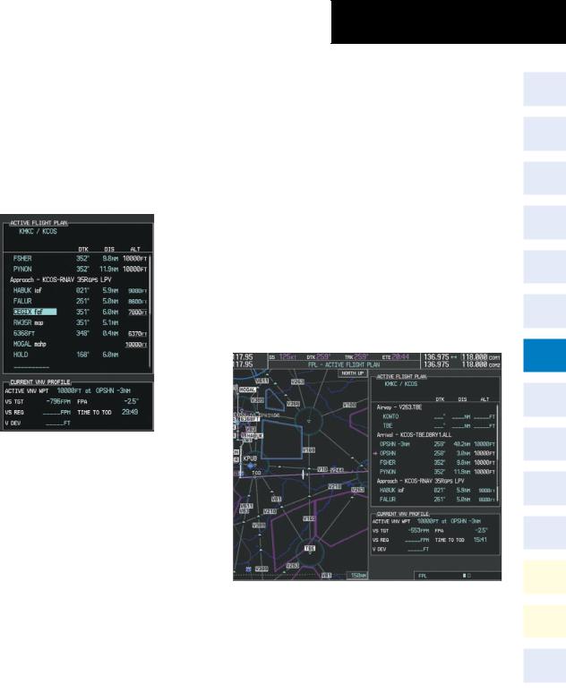
Altitude constraint values associated with the Final Approach Fix (FAF) and waypoints beyond the FAF cannot be designated for vertical guidance. These altitude values are always displayed as white text, as in Figure 7-36. Vertical guidance from the FAF to the Missed Approach Point (MAP) is given using the WAAS GPS altitude source, therefore, the displayed altitude values are for reference only.
SECTION 7 – NAVIGATION
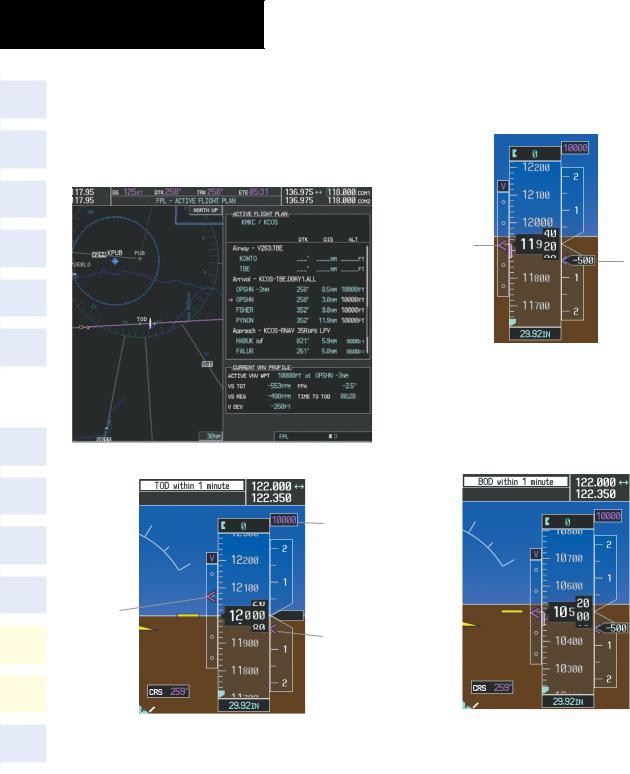
a)Press the VNV PROF Softkey to place the cursor in the target vertical speed field (VS TGT) as shown in Figure 7-37.
b)At this point, the descent vertical speed can be selected, or the FPA can be selected. Turn the large FMS Knob to select the desired selection field, then turn the small FMS Knob to enter the desired value.
Note the information now displayed in the ‘CURRENT VNV PROFILE’ box. Also, note the offset waypoint and a gray circle labeled ‘TOD’ are now displayed on the map. The gray circle marks the Top of Descent (TOD). In this example, after passing the TOD point, vertical guidance is provided that results in a -3.0 degree FPA descent to an altitude of 10,000 feet at the offset waypoint.
Figure 7-36 Vertical Guidance is Active to the FAF
14)As the aircraft approaches OPSHN, it may be desirable to adjust how fast, or steep, the upcoming descent will be. The default Flight Path Angle (FPA) is -2.5 degrees and a required vertical speed is computed to maintain the -2.5 FPA. To change the vertical flight path, perform the following steps.
Figure 7-37 Adjusting the Descent
c) Press the ENT Key.
190-00384-09 Rev. A |
Garmin G1000 Cockpit Reference Guide for the Cessna Nav III |
7-15 |
SECTION 7 – NAVIGATION
15)As seen in Figure 7-38, the aircraft is approaching TOD. Note the target vertical speed required to reach the selected altitude. The Vertical Deviation Indicator (VDI) and the Required Vertical Speed Indicator (RVSI) are now displayed on the PFD as shown in Figure 7-39.
16)Upon reaching TOD, a descent vertical speed is established which places the VSI pointer in line with the RVSI as shown in Figure 7-40.
|
|
|
Keep Vertical |
Align Indicated |
|
|
|
|
Deviation Pointer |
Vertical Speed |
|
|
|
|
Centered |
with Required |
|
|
|
|
|
|
Vertical Speed |
|
|
|
Figure 7-40 VDI & RVSI Showing Correctly Established Descent |
||
|
|
|
17) |
When the aircraft is one minute from the bottom |
|
|
|
|
|||
|
|
|
|
of descent (BOD) this is annunciated as shown |
|
|
|
|
|
in Figure 7-41. Upon reaching the OPSHN offset |
|
|
|
|
|
||
|
|
|
|
waypoint (three miles before OPSHN), the aircraft |
|
|
Figure 7-38 Approaching Top of Descent (TOD) |
|
will be at 10,000 feet. |
|
|
|
|
Target |
|
|
|
|
|
Altitude |
|
|
|
|
Vertical |
|
|
|
|
|
Deviation |
Required |
|
|
|
|
Indicator |
Vertical |
|
|
|
|
(VDI) |
Speed |
|
|
|
|
|
Indicator |
|
|
|
|
|
(RVSI) |
|
|
|
|
Figure 7-39 VDI & RVSI Upon Reaching Top of Descent (TOD) |
Figure 7-41 Approaching Bottom of Descent (BOD) at OPSHN |
|||
|
|
|
|
||
7-16 |
|
Garmin G1000 Cockpit Reference Guide for the Cessna Nav III |
190-00384-09 Rev. A |
||
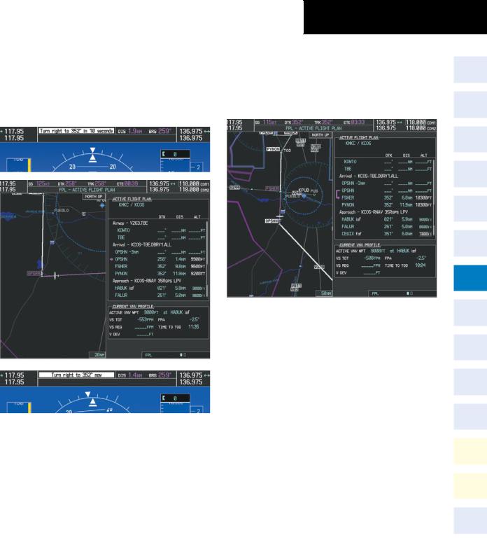
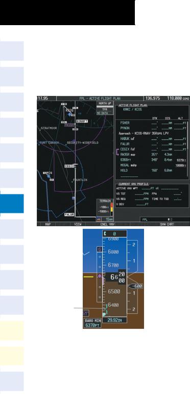
18)The aircraft is approaching OPSHN. The upcoming turn and next heading is annunciated at the top left of the PFD as seen in Figure 7-42. Initiate the turn and maneuver the aircraft on a track through the turn radius to intercept the magenta line for the OPSHN to FSHER leg and center the CDI.
SECTION 7 – NAVIGATION
19)After passing OPSHN, the next leg of the arrival turns magenta as shown in Figure 7-43. The magenta arrow in the flight plan list now indicates the OPSHN to FSHER leg of the arrival procedure is now active.
Figure 7-43 Tracking the OPSHN to FSHER Leg
20) The flight continues through the arrival procedure to PYNON (see Figure 7-44). At a point 31 nautical miles from the destination airport, the phase of flight scaling for the CDI changes to Terminal Mode and is annunciated by displaying ‘TERM’ on the HSI.
There will be a descent to HABUK in the next leg.
Note the TOD point on the map. Annunciations
Figure 7-42 Turn to intercept OPSHN to FSHER Leg for the upcoming turn and descent, as well as the VDI and RVSI, appear on the PFD as the flight progresses.
190-00384-09 Rev. A |
Garmin G1000 Cockpit Reference Guide for the Cessna Nav III |
7-17 |
SECTION 7 – NAVIGATION
21) Upon passing PYNON the approach procedure automatically becomes active. The approach may be activated at any point to proceed directly to the IAF. In this example, the aircraft has progressed through the final waypoint of the arrival and the flight plan has automatically sequenced to the IAF as the active leg, activating the approach procedure (see Figure 7-45).
Figure 7-45 Approach Leg is Now Active
To manually activate the approach procedure, perform the following steps:
a) Press the PROC Key.
b) Turn the large FMS Knob to highlight ‘ACTIVATE APPROACH’ as shown in Figure 7-46.
Figure 7-44 Approaching PYNON
Figure 7-46 Activate Missed Approach
c) Press the ENT Key to activate the approach.
7-18 |
Garmin G1000 Cockpit Reference Guide for the Cessna Nav III |
190-00384-09 Rev. A |
22)The IAF is the next waypoint. At the TOD, establish a descent vertical speed as previously discussed in Step 16. The aircraft altitude will be 9,000 feet upon reaching HABUK.
SECTION 7 – NAVIGATION
approach course becomes active. Note the BARO MIN Box is now displayed indicating the Decision Altitude entered when the approach was loaded.
Figure 7-47 Descending Turn to the Initial Approach Fix (IAF)
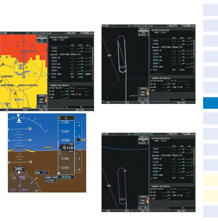
23)After crossing FALUR the next waypoint is the FAF. The flight phase changes to LPV on the HSI indicating the current phase of flight is in Approach Mode and the approach type is LPV. CDI scaling changes accordingly and is used much like a localizer when flying an ILS approach. The RVSI is no longer displayed and the VDI changes to the Glidepath Indicator (as shown in Figure 7-48) when the final
Figure 7-48 Descending to the FAF
The descent continues through the FAF (CEGIX) using the Glidepath Indicator, as one would use a glideslope indicator, to obtain an altitude “AT” 7,800 feet at the FAF. Note the altitude restriction lines over and under (‘At’) the altitude in the ‘ALT’ field in Figure 7-48.
190-00384-09 Rev. A |
Garmin G1000 Cockpit Reference Guide for the Cessna Nav III |
7-19 |
SECTION 7 – NAVIGATION
24)After crossing CEGIX, the aircraft continues following the glidepath to maintain the descent to “AT or ABOVE” 6,370 feet at the Missed Approach Point (MAP) (RW35R) as seen in Figure 7-49. Note the BARO MIN bug is now displayed on the altimeter.
Keep Vertical
Deviation Pointer
Centered
Figure 7-49 Descending to the Missed Approach Point
In this missed approach procedure, the altitude immediately following the MAP (in this case ‘6368ft’) is not part of the published procedure. It is a Course to Altitude (CA) leg which guides the aircraft along the runway centerline until the altitude required to safely make the first turn toward the MAHP is exceeded. In this case, if the aircraft altitude is below the specified altitude (6,368 feet) after crossing the MAP, a direct-to is established to provide a course on runway heading until an altitude of 6,368 feet reached. After reaching 6,368 feet, a direct-to is established to the published MAHP (MOGAL). If the aircraft altitude is above the specified altitude after crossing the MAP, a direct-to is established to the published fix (MOGAL) to begin the missed approach procedure. The altitude constraint value defaults to 400 feet AGL when there is no Course to Altitude defined in the published procedure.
In some missed approach procedures a Course to Altitude leg may be part of the published procedure. For example, the procedure dictates a climb to 5,500 feet, then turn left and proceed to the Missed Approach Hold Point (MAHP). The altitude would appear in the list of waypoints as ‘5500ft’. Again, if the aircraft altitude is lower than this prescribed altitude, a direct-to is established on a Course to Altitude leg when the missed approach procedure is activated.
25)Upon reaching the MAP, it is decided to execute a missed approach. Automatic waypoint sequencing is suspended past the MAP. Press the SUSP Softkey on the PFD to resume automatic waypoint sequencing through the missed approach procedure.
7-20 |
Garmin G1000 Cockpit Reference Guide for the Cessna Nav III |
190-00384-09 Rev. A |
|
|
SECTION 7 – NAVIGATION |
|
|
|
A direct-to is initiated to MOGAL, which is the |
26) The aircraft continues climbing to “AT or ABOVE” |
|
Missed Approach Hold Point (MAHP) as seen in |
10,000 feet at MOGAL. A holding pattern is |
|
Figure 7-50. The aircraft is climbing to 10,000 |
established at the MAHP (MOGAL) as shown in |
|
feet. The CDI flight phase now changes from LPV |
Figure 7-51. |
|
to MAPR as seen on the HSI. |
|
|
Figure 7-51 Establishing the Holding Pattern
27) The aircraft maintains 10,000 feet while following the magenta line through the hold as in Figure 7 52.
Figure 7-50 |
Missed Approach Active |
|
|
Figure 7-52 Hold Established |
|
190-00384-09 Rev. A |
Garmin G1000 Cockpit Reference Guide for the Cessna Nav III |
7-21 |