

α Series Simple Applicaton Controllers |
Menu Bar Functions 5 |
|
5.Menu Bar Functions
This chapter gives a brief description of the available functions contained in the Pull Down menus.
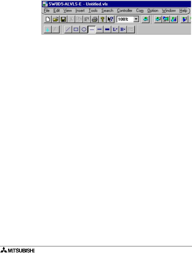
Menu bar 

5.1File
New (Crtl+N) - Creates a new file with windows in both the FBD and Monitoring in System Sketch window. When the FBD window and the system sketch monitor window have already been displayed, the dialog box to save the file under the display is viewed.
Open... (Crtl+O) - Opens an existing file with windows in both the FBD and Monitoring in System Sketch window. When the FBD window and the system sketch monitor window have already been displayed, the dialog box to save the file under the display is viewed.
Close - Closes existing active documents in both the FBD and System Sketch window, and the dialog box to preserve the file under the display is viewed.
Save (Crtl+S) - Saves (overwrites) the current file to its current name and directory. When creating new file, this process is same as “Save As...”.
Save As... - Saves the current file under a new name and or directory. The first time a file is saved this command will come up so that the file can be named.
Print Setup... - Selects a printer and printer connection from the Print Setup Dialog Box that appears on the screen.
Print Preview - Views the active document as it would appear if printed. This command is disabled if either of the FBD or Monitoring in System Sketch window is minimized.
Print... (Crtl+P) - A Print Dialog box appears onscreen for selecting options and Print data.
Export Registered User Func - The registered UserFunc data (User Function Bock) is exported (stored) to a designated folder; Thus, registering the UserFunc data (User Function Block) is possible from one PC to another.
Import Registered User Func - The exported UserFunc data (User Function Block) is imported from a designated folder; Thus, registering/transferring the UserFunc data (User Function Block) is possible from one PC to another.
Recent File(Max.8) - Displays the history of the file opened in the past. The histories are displayed up to 8 for the one preserved as a file. Moreover, by selecting the arbitrary file from the displayed history, and selecting; The file that has been opened in the past can be opened again.
Exit - Ends the VLS session. When the displayed file was not saved, the dialog box to preserve the file under the display is viewed.
5-1

α Series Simple Applicaton Controllers |
Menu Bar Functions 5 |
|
|
5.2Edit
Undo (Crtl+Z) - Cancels the Previous Instruction. There is only one level of Undo available.
Redo (Crtl+Y) - Cancels the Previous Undo Instruction. There is only one level of Redo available.
Cut (Crtl+N) - Removes the selected data from the Screen and place it to the Clipboard.
Copy (Crtl+C) - Copy the selected data to the Clipboard.
Paste (Crtl+V) - Adds the data from the Clipboard to the Program
Delete (Del) - Deletes the selected data from the program.
Select All (Crtl+A) - Select All the function blocks on the screen.
Insert Func - Inserts a new function block on the FBD window or on the Monitoring in System Sketch Window. Select the function block to be inserted. Click the position where the function block to be placed on the FBD window or the Monitoring in System Sketch Window.
Change Func - Changes the function block placed by the FBD window or the Monitoring in System Sketch Window. Select the function block to be placed newly after the icon to be altered is clicked.
Insert Logic - Inserts a new logic block on the FBD window or on the Monitoring in System Sketch Window. Select the logic block to be inserted. Click the position where the logic block is to be placed on the FBD window or on the Monitoring in System Sketch Window.
Change Logic - Changes the logic block placed by the FBD window or the Monitoring in System Sketch Window. Select the logic block to be put newly after the icon to be changed is selected.
5-2

α Series Simple Applicaton Controllers |
Menu Bar Functions 5 |
|
|
5.3View
Close (Open) System Sketch - Closes the System Sketch Screen. If the screen is closed, the title will change to Open System Sketch.
Close (Open) FBD - Closes the Function Block Diagram base. If closed, the menu option will change to Open FBD.
Standard Toolbar - When the Check mark appears, the Standard Toolbar will be displayed onscreen.
Controller Toolbar - When the Check mark appears, the Controller Toolbar will be displayed onscreen.
Drawing Toolbar - When the Check mark appears, the Drawing Toolbar will be displayed onscreen.
Accessories Toolbar - When the Check mark appears, the Accessories Toolbar will be displayed Onscreen.
Wiring Toolbar - When the Check mark appears, the Wiring Toolbar will be displayed onscreen.
Image Toolbar - When the Check mark appears, the Image Toolbar will be displayed onscreen.
User Function Toolbar - When the Check mark appears, the User Function Toolbar will be displayed onscreen.
Status Bar - When the Check mark appears, the Status Bar will be displayed Onscreen.
Zoom - Choose from 200 (Ctrl+PageUp), 150, 100 (Ctrl+Home), 75, 50 (Ctrl+PageDown), 25, or 10% zoom factors.
5-3

α Series Simple Applicaton Controllers |
Menu Bar Functions 5 |
|
|
5.4Insert
LCD Image - Displays the same content as the liquid crystal display of the α series. LCD image is active only in the Monitoring in System Sketch Window.
Comment - The FBD window and the Monitoring in System Sketch Window displays comment. The comment control statement is not limited to a number of strokes with this software.
Insert New Object... - Inserts the data made by other applications as a display panel item on the Monitoring in System Sketch Window.
Links... - This menu will be active when the selected object is the linked file. The object file must appear on the “Link” when inserting object via the “Insert New Object...” In this menu, the following is possible.
-Display the linked file information
-Update the linked file data
-Edit the linked file with the used source application. In this case, the application is opened.
When this object is double-clicked, the source application will be opened.
-Change the current file to other file.
-Break the link information. Therefore, the linked file is converted to AL-PCS/WIN-E data. In this case, the file cannot be edited with the source application.
Object - Opens the application in which the selected embedded or linked object was created thus editing is possible.
5.5Tools
Start Auto FBD Wizard - Starts the auto FBD wizard function. However, this command supports only the α series (Model: AL-**M*-*). This command is not available when the α2 Series controller is selected.
Renumber Signals - Updates the FB number of the icon placed on the FBD window and the Monitoring in System Sketch Window. When the function block is deleted after the program is constructed, the number of the icon becomes empty. The number allocated to the function block is updated when “Renumber Signals” is executed, and the number of the deleted icon is filled.
Replace Signals - The Replace Signals function allows the user to exchange a signal object assignment with other objects present on the FBD and system sketch windows.
5.6Search
By Comment - Searches for a Function Block by the attached comment. The comment does not have to be displayed nor is the search case sensitive. The text, however, must be an exact match. If a match is found, the block will be highlighted.
By Signal Number - Search for the Function Block by the coded signal number. The alphanumeric sequence as it appears onscreen - one letter followed by two numbers. The letters are not case sensitive. Ex. - M01, i06, B12.
5-4

α Series Simple Applicaton Controllers |
Menu Bar Functions 5 |
|
|
5.7Controller
Write to Controller - Write the program from the AL-PCS/WIN-E to the memory of the α series. The contents of the α series memory will be completely overwritten.
Read from Controller - Uploads the contents of the α series memory into the VLS program. The current program in VLS will be overwritten.
Verify Controller data with VLS - Verify the data in the FBD matches the data in the α series memory.
Clear Controller Contents - Clears the memory of the α series that is connected to the PC.
Diagnosis of Controller - Brings up a dialog box with the following information about the connected α series:
Table 5.1: Diagnosis of Controller
|
|
|
|
|
|
|
|
|
|
|
|
|
|
Items |
|
Description |
α |
α2 |
|
|
|
|
|
|
Series |
Series |
|
||
|
|
|
|
|
|
|
|
||
|
|
|
Version |
Version number; Ex. 1.60 |
|
|
|
||
|
|
|
|
|
|
|
|
||
|
|
|
Input Terminals |
Number of input terminals |
|
|
|
||
|
|
|
|
|
|
|
|
||
|
|
|
Analog Inputs |
Number of analog inputs. |
|
|
|
||
|
|
|
|
|
|
|
|
||
|
|
|
Output Terminals |
Number of output terminals |
|
|
|
||
|
|
|
|
|
|
|
|
|
|
|
|
|
Input Type |
DC |
DC input type |
|
|
|
|
|
|
|
|
|
|
||||
|
|
|
AC |
AC input type |
|
||||
|
|
|
|
|
|
|
|
||
|
|
|
|
|
|
|
|
|
|
|
|
|
Error Code |
See Note 1 (table 5.2) |
|
|
|
||
|
|
|
|
|
|
|
|
|
|
|
|
|
Run Status |
Running |
α series into Run mode |
|
|
|
|
|
|
|
|
|
|
||||
|
|
|
Stopped |
α series into Stop mode |
|
||||
|
|
|
|
|
|
|
|
||
|
|
|
|
|
|
|
|
|
|
|
|
|
|
|
Enable |
It is possible to write program data |
|
|
|
|
|
|
|
|
from the AL-PCS/WIN-E. |
|
|
|
|
|
|
|
Program write |
|
|
|
|
||
|
|
|
|
|
|
||||
|
|
|
Disable |
It is impossible to write program |
|
||||
|
|
|
|
|
|
|
|
||
|
|
|
|
|
data from the AL-PCS/WIN-E. |
|
|
|
|
|
|
|
|
|
|
|
|
|
|
|
|
|
|
|
|
|
|
|
|
|
|
|
|
|
Going |
Clock is going. |
|
|
|
|
|
|
|
|
|
|
|
|
|
|
|
|
Clock Status |
|
Clock stops. Set current time into |
|
|
|
|
|
|
|
Stopped |
the α series. The clock will be |
|
||||
|
|
|
|
|
|
|
|
||
|
|
|
|
|
|
going. |
|
|
|
|
|
|
|
|
|
|
|
|
|
|
|
|
User Memory |
Used memory size / Total memory size |
|
|
|
||
|
|
|
|
|
|
|
|
|
|
|
|
|
Used Blocks |
Used function (logic) blocks / Maximum function |
|
|
|
||
|
|
|
(logic) blocks allowed |
|
|||||
|
|
|
|
|
|
|
|
||
|
|
|
|
|
|
|
|
||
|
|
|
Max. Scan Time (ms) |
Maximum 1 scan time |
- |
|
|
||
|
|
|
|
|
|
|
|
||
|
|
|
Min. Scan Time (ms) |
Minimum 1 scan time |
- |
|
|
||
|
|
|
|
|
|
|
|
||
|
|
|
Current Scan Time (ms) |
Current scan time |
- |
|
|
||
|
|
|
|
|
|
|
|
||
|
|
|
Dedicated ComPort Error |
See Note 2 (table 5.3) |
- |
|
|
||
|
|
|
|
|
|
|
|
|
|
|
|
|
|
|
Permission |
Copy program α2 → |
- |
|
|
|
|
|
|
|
|
|
|||
|
|
|
|
|
|
cassette possible |
V2.20 |
|
|
|
|
|
Copy to Memory Cassette |
|
|
|
|||
|
|
|
|
|
|
|
|
||
|
|
|
Forbidden |
Copy program α2 → |
- |
|
|
||
|
|
|
|
|
|
||||
|
|
|
|
|
|
|
|||
|
|
|
|
|
|
cassette not possible |
V2.20 |
|
|
|
|
|
|
|
|
|
|
||
|
|
|
|
|
|
|
|
||
|
|
|
Program file name |
VLS file name of user program |
|
|
|
||
|
|
|
|
|
|
|
|
|
|
|
|
|
|
|
|
|
|
|
|
|
|
|
|
|
|
|
|
|
|
|
|
|
|
|
|
|
5-5 |
|
|
|
|
|
|
|
|
|
|
|
|
|
|
|
|
|
|
|
|
|
|

α Series Simple Applicaton Controllers Menu Bar Functions 5
Table 5.1: Diagnosis of Controller
|
|
|
|
|
|
|
|
|
|
Items |
Description |
α |
α2 |
|
|
|
|
Series |
Series |
|
|||
|
|
|
|
|
|
||
|
|
|
Response from |
When the Check mark appears, there is |
- |
|
|
|
|
|
GSM modem |
response. |
|
||
|
|
|
|
|
|
||
|
|
|
|
|
|
|
|
|
|
|
Initial successful |
When the Check mark appears, initialization is |
- |
|
|
|
|
|
successful. |
|
|||
|
|
|
|
|
|
|
|
|
|
|
|
|
|
|
|
|
|
|
Set PIN Code |
When the Check mark appears, α2 series has |
- |
|
|
|
|
|
the correct pin code setting. |
|
|||
|
|
|
|
|
|
|
|
|
|
|
|
|
|
|
|
|
|
|
Network |
When the Check mark appears, network |
|
|
|
|
|
|
registration |
- |
|
|
|
|
|
|
registration is finished. |
|
|||
|
|
|
finished |
|
|
|
|
|
|
|
|
|
|
|
|
|
|
|
|
|
|
|
|
|
|
|
GSM CME Error |
When the Check mark appears, GSM SME |
- |
|
|
|
|
|
Error has occurred. |
|
|||
|
|
|
|
|
|
|
|
|
|
|
|
|
|
|
|
|
|
Status |
GSM CMS Error |
When the Check mark appears, GSM SMS |
- |
|
|
|
|
Error has occurred. |
|
||||
|
|
|
|
|
|
|
|
|
|
|
|
|
|
|
|
|
GSM |
|
Remote Access |
When the Check mark appears, remote access |
- |
|
|
|
|
successful |
is successful |
|
|||
|
|
|
|
|
|
||
|
|
|
|
|
|
|
|
|
|
|
SMS is sending |
When the Check mark appears, SMS is sending |
- |
|
|
|
|
|
or retrying |
or retrying |
|
||
|
|
|
|
|
|
||
|
|
|
|
|
|
|
|
|
|
|
SMS is waiting |
When the Check mark appears, SMS is waiting |
- |
|
|
|
|
|
for sending |
for sending status |
|
||
|
|
|
|
|
|
||
|
|
|
|
|
|
|
|
|
|
|
SMS is failed in |
When the Check mark appears, SMS has failed |
- |
|
|
|
|
|
sending |
to send |
|
||
|
|
|
|
|
|
||
|
|
|
|
|
|
|
|
|
|
|
SMS failed in |
When the Check mark appears, SMS failed in |
|
|
|
|
|
|
sending due to |
- |
|
|
|
|
|
|
sending due to incorrect setting |
|
|||
|
|
|
wrong setting |
|
|
|
|
|
|
|
|
|
|
|
|
|
|
|
|
|
|
|
|
|
|
CME Error |
Please see manual for GSM modem. |
- |
|
|
|
|
|
|
|
|
|
|
|
|
|
CMS Error |
Please see manual for GSM modem. |
- |
|
|
|
|
|
|
|
|
|
|
|
|
|
Signal Strength (%) |
This status shows state of the radio wave on |
- |
|
|
|
|
|
GSM network. See Note 3 (Table 5.4) |
|
||||
|
|
|
|
|
|
|
|
|
|
|
|
|
|
|
|
|
|
|
|
|
|
|
|
Note 1: Error Codes for α Series Main Module
The α series returns from error condition when the power supply is reentered after the error causation is obviated.
Table 5.2: Error Codes for α Series Main Module
|
|
|
|
|
Message |
Description |
|
|
No Error |
Error has not occurred in the α series. |
|
|
|
|
|
|
EEPROM fail |
Memory cassette is incorrect. Please check the memory cassette is correctly |
|
|
installed, into α series. |
|
|
|
|
|
|
|
|
|
|
|
|
Program data is incorrect. The program included in the memory cassette has |
|
|
Other Error |
more points of input and/or output than is allowed in the α series. Please check |
|
|
model type, and download program data into α series. If the α series has not |
|
|
|
|
|
|
|
|
recovered please consult a Mitsubishi Distributor. |
|
|
|
|
|
|
|
|
|
5-6
α Series Simple Applicaton Controllers Menu Bar Functions 5
Note 2: Dedicated ComPort Error
Please check the following points for Dedicated ComPort Error.
Table 5.3: Dedicated ComPort Error
|
|
|
|
|
Message |
Description |
|
|
|
|
|
|
No Errors |
No error with communication via AL2-GSM-CAB. |
|
|
|
|
|
|
|
Parity, overrun or framing error occurred during communication via AL2-GSM- |
|
|
|
CAB. |
|
|
|
Checking Points: |
|
|
Parity etc. |
Check the connection, data format (Data bit, Parity, Stop bit and Baud rate) and |
|
|
communication timing during communication via AL2-GSM-CAB. |
|
|
|
|
|
|
|
|
If the connection, data format and communication timing are correct, thus |
|
|
|
possibility to have received the influence of the electrical noise may have |
|
|
|
caused the problem. |
|
|
|
|
|
|
|
Time-out error occurred during communication via AL2-GSM-CAB. |
|
|
Time-out |
Checking Points: |
|
|
Check the connection, data format (Data bit, Parity, Stop bit and Baud rate) and |
|
|
|
|
|
|
|
|
communication timing during communication via AL2-GSM-CAB. |
|
|
|
|
|
|
|
|
|
Note 3: Signal Strength
This status shows the state of the radio wave on GSM network.
Table 5.4: Signal Strength
|
Value (%) |
Reception Level of Radio Wave |
|
|
0 |
-113dBm or less |
|
|
|
|
|
|
3 |
-111dBm |
|
|
|
|
|
|
6~96 |
-109 ~ -53dBm |
|
|
|
|
|
|
100 |
-51dBm or more |
|
|
|
|
|
|
0 |
Not received radio wave |
|
|
|
|
|
|
|
|
|
5-7

α Series Simple Applicaton Controllers |
Menu Bar Functions 5 |
|
|
Check Used Memory (Memory Configuration and Usage) - Check the amount of the following items in the displayed file.
Table 5.5: Check Used Memory (Memory Configuration and Usage)
|
|
|
|
|
|
|
Items |
Description |
α |
α2 |
|
|
Series |
Series |
|
||
|
|
|
|
||
|
Used Memory |
Used memory / Total memory |
|
|
|
|
|
|
|
|
|
|
Used Block(s) |
Used function (logic) blocks / Maximum blocks allowed |
|
|
|
|
|
|
|
|
|
|
Input Signal(s) |
Number of input terminals |
|
|
|
|
|
|
|
|
|
|
Communication |
|
|
|
|
|
Memory |
Used memories for communication by dedicated protocol |
- |
|
|
|
(byte(s)) |
|
|
|
|
|
|
|
|
|
|
|
|
|
|
|
|
Simulation - The simulation mode will run the program in the AL-PCS/WIN-E without an α series. This is very useful to check your program prior to transferring it to the actual system.
Drive Controller - Change the connected α series into Run or Stop mode.
Monitor/Test - Monitor the status of the connected α series from the AL-PCS/WIN-E.
5.8Com
Configuration - Sets the Configuration of the communication port. The user can choose between a modem or a Com port to communicate with the α series.
Connect Line - Dial a Telephone number by invoking the Ring Telephone dialog.
Disconnect Line - Disconnect an ongoing call. An active Modem line should be disconnected before it can be used again for communication.
5-8

α Series Simple Applicaton Controllers |
Menu Bar Functions 5 |
|
|
5.9Option
Select Controller Type - It is possible to change model type (series, I/O points) for programming. This menu is displayed in FBD window only.
Change Input/Output Pins... - It is possible to change number of I/O pins for the user function block. This menu is displayed in the Sub FBD window only.
User Defined Icons - Import your own user defined icons for the signal icon and the function icon (Technical, Fancy).
Function Icon Set - Select the icon set to be displayed on screen from the LCD Image, the system icon (Technical, Fancy) or user icon (Technical, Fancy).
Set Wire Color - Set the wire color for the Edit and Simulation modes on the FBD window.
Set Base Color - Set base color of the FBD (Function Block Diagram) or the Monitoring in System Sketch base.
Date Format - Select one of the following formats in which the calendar date will be shown. mm/dd/yy, dd/mm/yy, yyyy/mm/dd.
Change Current Time - Change the current time in α series.
Radio Clock... - Set the connection port to use the Radio clock (DCF77). This option is not available when the α series controller is selected.
GSM and Serial Communication... - Sets modem and GSM modem settings for remote maintenance and serial communications for the dedicated protocol.
Dedicated Communication... - Set station number and communication data for dedicated protocol communication.
Analog Input... - Sets the temperature scale of the analog inputs to use with the AL2-2PT- ADP and AL2-2TC-ADP. This option is not available when the α series controller is selected.
Select Font - Changes font all windows.
PasswordEnter Password for program protection.(α, α2 series)
-Enter Password for program read protection. (α2 version 2.20 or later)
-Set the "Copy to Memory Cassette Protection". (α2 version 2.20 or later)
Grid - Choose the Horizontal and Vertical Grid line spacing from 2 to 32.
Show Grid - Hide or Display the Grid lines on the FBD window.
5.10Window
Cascade - Use this command to arrange multiple open windows in an overlapped fashion.
Tile - Use this command to vertically arrange multiple open windows in a non-overlapped fashion.
1 Monitoring in System Sketch - Open the Monitoring in System Sketch Window for monitoring or editing.
2 FBD - Open the Function Block Diagram base for monitoring or editing.
3 Sub FBD (F***) - Open the Sub Function Block Diagram base for monitoring or editing.
5-9

α Series Simple Applicaton Controllers |
Menu Bar Functions 5 |
|
|
5.11Help
Contents - Shows the Table of Contents of the Help Function. The user can click on the desired chapter and the help file will appear onscreen.
Search for Help on... - Displays the opening screen of the Help command. Choose from a list of instructions and reference information on the features of the AL-PCS/WIN-E.
How to Use Help - Provides information on how to use and customize the help function.
About SW0D5-ALVLS-E... - Provides the Version number and Copyright notice for the AL- PCS/WIN-E package.
5-10