

α Series Simple Application Controllers |
Function Block Diagram (FBD) Programming 6 |
|
|
6.4Connection (Wiring) between Icons
6.4.1Input and Output Pins
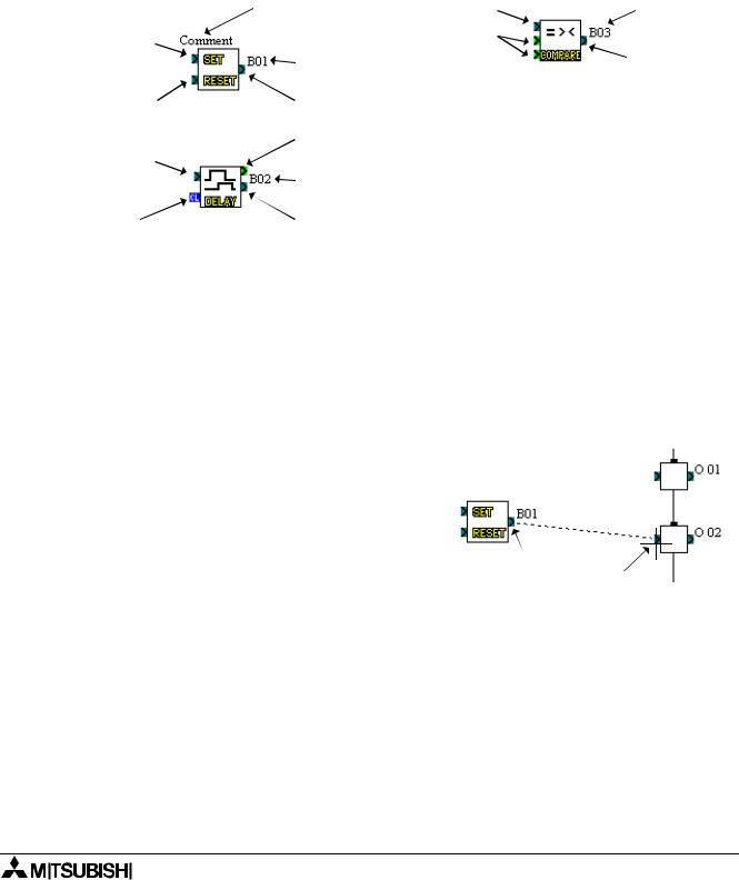
The small rectangles present on left and right side of icon are known as pins. These pins are of 4 types, Bit Input (Clear) pin, Bit Output pin, Word Input pin and Word Output pin. Pins which are present on the left side of icon are known as INPUT pins. Pins which are present on the right side of icon are known as OUTPUT pins.
The pin is enclosed in a light green square on the AL-PCS/WIN-E display to differentiate it from a bit pin.
|
Comment |
Bit Input Pin |
Block Number |
Bit Input Pin |
|
Word Input |
|
|
Pin |
|
|
|
Block Number |
Bit Output Pin |
|
|
|
||
Bit Intput Pin |
Bit Output Pin |
|
|
|
Word Output Pin |
|
|
Bit Input Pin |
|
|
|
|
Block Number |
|
|
Bit Intput |
Bit Output Pin |
|
|
(Clear) Pin |
|
|
|
6.4.2Connection (Wiring) between Icons
The wiring tool graphically represents, in the form of terminated lines, the connections made between the inputs, outputs, signals and functions present in the FBD window.
The Wiring tool can be invoked by clicking the Wiring Toolbar. Placed an the left hand side of the FBD windows.
To connect between icons:
1)Click the Wiring toolbar
2)Click the input or output pin on the icon to connect the wire
3)Click the output or input pin on the target icon to make a connection between the two entities.
4) If the pins have not physically connected, |
|
return to part 2). |
Click |
|
Click |
5)The wiring toolbar will remain activated until the user clicks on any other toolbar or on vacant space within the FBD base.
6-15

α Series Simple Application Controllers |
Function Block Diagram (FBD) Programming 6 |
|
|
Note:
Bit Output Pins are connected to Bit Input Pins and Similarly Word Output Pins are connected to Word Input Pins. However, Bit pins cannot be connected to word pins, but output pins can connect to multiple input pins.
In the following cases an appropriate error message occurs:
•Input Pin cannot be connected to Input Pin.
•Output Pin cannot be connected to Output Pin.
•Bit Pin can not be connected to Word Pin.
•Input Pin can not have more than one wire connected to it.
•No pin is located in this position.
6-16