

- •Introduction
- •Participants
- •Contents
- •List of Figures
- •List of Tables
- •1. Overview
- •1.1 Scope
- •1.2 Purpose
- •1.3 Reference model
- •2. References
- •3. Definitions
- •4. Abbreviations and acronyms
- •5. Service specific convergence sublayer
- •5.1 ATM convergence sublayer
- •5.1.1 Convergence sublayer service definition
- •5.1.2 Data/Control plane
- •5.1.2.1 PDU formats
- •5.1.2.2 Classification
- •5.1.2.2.1 VP-switched mode
- •5.1.2.2.2 VC-switched mode
- •5.1.2.3 Payload header suppression
- •5.1.2.3.1 PHS for VP-switched ATM connections
- •5.1.2.3.2 PHS for VC-switched ATM connections
- •5.1.2.4 Signaling procedure
- •5.2 Packet convergence sublayer
- •5.2.1 MAC SDU format
- •5.2.2 Classification
- •5.2.3 Classification within the CS
- •5.2.4 Payload header suppression
- •5.2.4.1 PHS operation
- •5.2.4.2 PHS signaling
- •5.2.5.2 IEEE Std 802.3/Ethernet CS classifiers
- •5.2.6 IEEE Std 802.1Q-1998 VLAN specific part
- •5.2.6.1 IEEE Std 802.1Q-1998 VLAN CS PDU format
- •5.2.6.2 IEEE Std 802.1Q-1998 CS classifiers
- •5.2.7 IP specific part
- •5.2.7.1 IP CS PDU format
- •5.2.7.2 IP classifiers
- •6. MAC common part sublayer (CPS)
- •6.1 MAC service definition
- •6.1.1 Primitives
- •6.1.1.1 MAC_CREATE_CONNECTION.request
- •6.1.1.1.1 Function
- •6.1.1.1.2 Semantics of the service primitive
- •6.1.1.1.3 When generated
- •6.1.1.1.4 Effect of receipt
- •6.1.1.2 MAC_CREATE_CONNECTION.indication
- •6.1.1.2.1 Function
- •6.1.1.2.2 Semantics of the service primitive
- •6.1.1.2.3 When generated
- •6.1.1.2.4 Effect of receipt
- •6.1.1.3 MAC_CREATE_CONNECTION.response
- •6.1.1.3.1 Function
- •6.1.1.3.2 Semantics of the service primitive
- •6.1.1.3.3 When generated
- •6.1.1.3.4 Effect of receipt
- •6.1.1.4 MAC_CREATE_CONNECTION.confirmation
- •6.1.1.4.1 Function
- •6.1.1.4.2 Semantics of the service primitive
- •6.1.1.4.3 When generated
- •6.1.1.4.4 Effect of receipt
- •6.1.1.5 Changing an existing connection
- •6.1.1.6 MAC_TERMINATE_CONNECTION.request
- •6.1.1.6.1 Function
- •6.1.1.6.2 Semantics of the service primitive
- •6.1.1.6.3 When generated
- •6.1.1.6.4 Effect of receipt
- •6.1.1.7 MAC_TERMINATE_CONNECTION.indication
- •6.1.1.7.1 Function
- •6.1.1.7.2 Semantics of the service primitive
- •6.1.1.7.3 When generated
- •6.1.1.7.4 Effect of receipt
- •6.1.1.8 MAC_TERMINATE_CONNECTION.response
- •6.1.1.8.1 Function
- •6.1.1.8.2 Semantics of the service primitive
- •6.1.1.8.3 When generated
- •6.1.1.8.4 Effect of receipt
- •6.1.1.9 MAC_TERMINATE_CONNECTION.confirmation
- •6.1.1.9.1 Function
- •6.1.1.9.2 Semantics of the service primitive
- •6.1.1.9.3 When generated
- •6.1.1.9.4 Effect of receipt
- •6.1.1.10 MAC_DATA.request
- •6.1.1.10.1 Function
- •6.1.1.10.2 Semantics of the service primitive
- •6.1.1.10.3 When generated
- •6.1.1.10.4 Effect of receipt
- •6.1.1.11 MAC_DATA.indication
- •6.1.1.11.1 Function
- •6.1.1.11.2 Semantics of the service primitive
- •6.1.1.11.3 When generated
- •6.1.1.11.4 Effect of receipt
- •6.1.2 MAC service stimulation of dynamic service messages
- •6.2 Data/Control plane
- •6.2.1 Addressing and connections
- •6.2.2 MAC PDU formats
- •6.2.2.1 MAC header formats
- •6.2.2.1.1 Generic MAC header
- •6.2.2.1.2 Bandwidth Request Header
- •6.2.2.2 MAC subheaders
- •6.2.2.2.1 Fragmentation subheader
- •6.2.2.2.2 Grant Management subheader
- •6.2.2.2.3 Packing subheader
- •6.2.2.3 MAC Management Messages
- •6.2.2.3.1 Downlink Channel Descriptor (DCD) message
- •6.2.2.3.2 Downlink Map (DL-MAP) message
- •6.2.2.3.3 Uplink Channel Descriptor message
- •6.2.2.3.4 Uplink Map (UL-MAP) message
- •6.2.2.3.5 Ranging Request (RNG-REQ) message
- •6.2.2.3.6 Ranging response (RNG-RSP) message
- •6.2.2.3.7 Registration Request (REG-REQ) message
- •6.2.2.3.8 Registration Response (REG-RSP) message
- •6.2.2.3.9 Privacy key management messages (PKM-REQ/PKM-RSP)
- •6.2.2.3.9.1 Security Association Add (SA Add) message
- •6.2.2.3.9.2 Authorization Request (Auth Request) message
- •6.2.2.3.9.3 Authorization Reply (Auth Reply) message
- •6.2.2.3.9.4 Authorization Reject (Auth Reject) message
- •6.2.2.3.9.5 Key Request message
- •6.2.2.3.9.6 Key Reply message
- •6.2.2.3.9.7 Key Reject message
- •6.2.2.3.9.8 Authorization Invalid message
- •6.2.2.3.9.9 TEK Invalid message
- •6.2.2.3.9.10 Authentication Information (Authent Info) message
- •6.2.2.3.10.1 SS-Initiated dynamic service addition (DSA)
- •6.2.2.3.10.2 BS-Initiated DSA
- •6.2.2.3.11.1 SS-Initiated DSA
- •6.2.2.3.11.2 BS-Initiated DSA
- •6.2.2.3.18 Multicast Polling Assignment Request (MCA-REQ) message
- •6.2.2.3.19 Multicast Polling Assignment Response (MCA-RSP) message
- •6.2.2.3.20 Downlink Burst Profile Change Request (DBPC-REQ) message
- •6.2.2.3.21 Downlink Burst Profile Change Response (DBPC-RSP) message
- •6.2.2.3.22 Reset Command (RES-CMD) message
- •6.2.2.3.23 SS Basic Capability Request (SBC-REQ) message
- •6.2.2.3.24 SS Basic Capability Response (SBC-RSP) message
- •6.2.2.3.25 Clock Comparison (CLK-CMP) message
- •6.2.2.3.26 De/Re-register Command (DREG-CMD) message
- •6.2.2.3.27 DSx Received (DSX-RVD) message
- •6.2.2.3.28 Config File TFTP Complete (TFTP-CPLT) message
- •6.2.2.3.29 Config File TFTP Complete Response (TFTP-RSP) message
- •6.2.3 Construction and transmission of MAC PDUs
- •6.2.3.1 Conventions
- •6.2.3.2 Concatenation
- •6.2.3.3 Fragmentation
- •6.2.3.4 Packing
- •6.2.3.4.1 Packing fixed-length MAC SDUs
- •6.2.3.4.2 Packing variable-length MAC SDUs
- •6.2.3.4.2.1 Interaction with fragmentation
- •6.2.3.5 CRC calculation
- •6.2.3.6 Encryption of MAC PDUs
- •6.2.4 ARQ mechanism
- •6.2.5 Uplink scheduling service
- •6.2.5.1 Unsolicited Grant Service
- •6.2.5.2 Real-Time Polling Service
- •6.2.5.3 Non-Real-Time Polling Service
- •6.2.5.4 Best Effort service
- •6.2.6 Bandwidth allocation and request mechanisms
- •6.2.6.1 Requests
- •6.2.6.2 Grants per connection (GPC) mode
- •6.2.6.3 Grants per subscriber station (GPSS) mode
- •6.2.6.4 Polling
- •6.2.6.4.1 Unicast
- •6.2.6.4.2 Multicast and broadcast
- •6.2.6.4.3 Poll-me bit
- •6.2.7 MAC support of PHY
- •6.2.7.1 Unframed Frequency Division Duplexing (FDD)
- •6.2.7.2 Framed (burst) FDD
- •6.2.7.3 Time Division Duplexing (TDD)
- •6.2.7.4 Downlink map
- •6.2.7.5 Uplink map
- •6.2.7.5.1 Uplink timing
- •6.2.7.5.1.1 Uplink timing with unframed PHY
- •6.2.7.5.1.2 Uplink timing with framed PHY
- •6.2.7.5.2 Uplink minislot definition
- •6.2.7.5.3 Uplink interval definition
- •6.2.7.5.3.1 Request IE
- •6.2.7.5.3.2 Initial Maintenance IE
- •6.2.7.5.3.3 Station Maintenance IE
- •6.2.7.5.3.4 Data Grant Burst Type IEs
- •6.2.7.5.3.5 Null IE
- •6.2.7.5.3.6 Empty IE
- •6.2.7.6 Map relevance and synchronization
- •6.2.7.6.1 Map relevance for framed PHY systems
- •6.2.7.6.2 Map relevance for unframed PHY systems
- •6.2.8 Contention resolution
- •6.2.8.1 Transmission opportunities
- •6.2.9 Network entry and initialization
- •6.2.9.1 Scanning and synchronization to the downlink
- •6.2.9.2 Obtain downlink parameters
- •6.2.9.3 Obtain uplink parameters
- •6.2.9.4 Message flows during scanning and uplink parameter acquisition
- •6.2.9.5 Initial ranging and automatic adjustments
- •6.2.9.6 Ranging parameter adjustment
- •6.2.9.7 Negotiate basic capabilities
- •6.2.9.8 SS authorization and key exchange
- •6.2.9.9 Registration
- •6.2.9.9.1 IP version negotiation
- •6.2.9.10 Establish IP connectivity
- •6.2.9.11 Establish time of day
- •6.2.9.12 Transfer operational parameters
- •6.2.9.13 Establish provisioned connections
- •6.2.10 Ranging
- •6.2.10.1 Downlink burst profile management in framed operation
- •6.2.11 Update of channel descriptors
- •6.2.12 Assigning SSs to multicast groups
- •6.2.13 Quality of Service
- •6.2.13.1 Theory of operation
- •6.2.13.2 Service flows
- •6.2.13.3 Object model
- •6.2.13.4 Service classes
- •6.2.13.5 Authorization
- •6.2.13.6 Types of service flows
- •6.2.13.6.1 Provisioned service flows
- •6.2.13.6.2 Admitted service flows
- •6.2.13.6.3 Active service flows
- •6.2.13.7 Preprovisioned service flow creation
- •6.2.13.7.1 Static operation
- •6.2.13.7.2 Dynamic service flow creation
- •6.2.13.7.2.3 Dynamic service flow modification and deletion
- •6.2.13.8 Dynamic service
- •6.2.13.8.1 Connection establishment
- •6.2.13.8.2 Dynamic service flow state transitions
- •6.2.13.8.3 Dynamic Service Addition (DSA)
- •6.2.13.8.3.1 SS-initiated DSA
- •6.2.13.8.3.2 DSA state transition diagrams
- •6.2.13.8.4 Dynamic Service Change (DSC)
- •6.2.13.8.4.1 SS-initiated DSC
- •6.2.13.8.4.2 BS-initiated DSC
- •6.2.13.8.4.3 DSC state transition diagrams
- •6.2.13.8.5 Connection release
- •6.2.13.8.5.1 SS-initiated DSD
- •6.2.13.8.5.2 BS-initiated DSD
- •6.2.13.8.5.3 DSD state transition diagrams
- •7. Privacy sublayer
- •7.1 Architecture
- •7.1.1 Packet data encryption
- •7.1.2 Key management protocol
- •7.1.3 Security Associations
- •7.1.4 Mapping of connections to SAs
- •7.1.5 Cryptographic Suite
- •7.2 PKM protocol
- •7.2.1 SS authorization and AK exchange overview
- •7.2.2 TEK exchange overview
- •7.2.3 Security capabilities selection
- •7.2.4 Authorization state machine
- •7.2.4.1 States
- •7.2.4.2 Messages
- •7.2.4.3 Events
- •7.2.4.4 Parameters
- •7.2.4.5 Actions
- •7.2.5 TEK state machine
- •7.2.5.1 States
- •7.2.5.2 Messages
- •7.2.5.3 Events
- •7.2.5.4 Parameters
- •7.2.5.5 Actions
- •7.3 Dynamic SA creation and mapping
- •7.3.1 Dynamic SA creation
- •7.3.2 Dynamic mapping of SA
- •7.4 Key usage
- •7.4.1 BS key usage
- •7.4.1.1 AK key lifetime
- •7.4.1.2 AK transition period on BS side
- •7.4.1.3 BS usage of AK
- •7.4.1.4 TEK lifetime
- •7.4.1.5 BS usage of TEK
- •7.4.2 SS key usage
- •7.4.2.1 SS reauthorization
- •7.4.2.2 SS usage of AK
- •7.4.2.3 SS usage of TEK
- •7.5 Cryptographic methods
- •7.5.1 Data encryption with DES
- •7.5.2 Encryption of TEK with 3-DES
- •7.5.3 Calculation of HMAC digests
- •7.5.4 Derivation of TEKs, KEKs, and message authentication keys
- •7.5.4.1 DES Keys
- •7.5.4.2 3-DES KEKs
- •7.5.4.3 HMAC authentication keys
- •7.5.5 Public-key encryption of authorization key
- •7.5.6 Digital signatures
- •7.6 Certificate profile
- •7.6.1 Certificate format
- •7.6.1.1 tbsCertificate.validity.notBefore and tbsCertificate.validity.notAfter
- •7.6.1.2 tbsCertificate.serialNumber
- •7.6.1.3 tbsCertificate.signature and signatureAlgorithm
- •7.6.1.4 tbsCertificate.issuer and tbsCertificate.subject
- •7.6.1.4.1 Manufacturer certificate
- •7.6.1.4.2 SS certificate
- •7.6.1.5 tbsCertificate.subjectPublicKeyInfo
- •7.6.1.6 tbsCertificate.issuerUniqueID and tbsCertificate.subjectUniqueID
- •7.6.1.7 tbsCertificate.extensions
- •7.6.1.7.1 SS certificates
- •7.6.1.7.2 Manufacturer certificates
- •7.6.1.8 signatureValue
- •7.6.2 SS certificate storage and management in the SS
- •7.6.3 Certificate processing and management in the BS
- •8. Physical layer
- •8.1 Physical layer (PHY) service specification
- •8.1.1 Scope
- •8.1.2 PHY functions
- •8.1.3 PHY SAP management
- •8.1.3.1 PHY MIB and generic SET/GET primitives
- •8.1.3.2 Parameter sets (vectors)
- •8.1.3.3 PHY_SCHEDPARAM.request
- •8.1.3.3.1 Function
- •8.1.3.3.2 Semantics of the service primitive
- •8.1.3.3.3 When generated
- •8.1.3.3.4 Effect of receipt
- •8.1.3.4 PHY_SCHEDPARAM.response
- •8.1.3.4.1 Function
- •8.1.3.4.2 Semantics of the service primitive
- •8.1.3.4.3 When generated
- •8.1.3.4.4 Effect of receipt
- •8.1.3.5 PHY_DCD.indication
- •8.1.3.5.1 Function
- •8.1.3.5.2 Semantics of the service primitive
- •8.1.3.5.3 When generated
- •8.1.3.5.4 Effect of receipt
- •8.1.3.6 PHY_DCD.request
- •8.1.3.7 Function
- •8.1.3.7.1 Semantics of the service primitive
- •8.1.3.7.2 When generated
- •8.1.3.7.3 Effect of receipt
- •8.1.3.8 PHY_DCD.confirmation
- •8.1.3.8.1 Function
- •8.1.3.8.2 Semantics of the service primitive
- •8.1.3.8.3 When generated
- •8.1.3.8.4 Effect of receipt
- •8.1.3.9 PHY_DCD primitives example
- •8.1.3.10 PHY_UCD.indication
- •8.1.3.10.1 Function
- •8.1.3.10.2 Semantics of the service primitive
- •8.1.3.10.3 When generated
- •8.1.3.10.4 Effect of receipt
- •8.1.3.11 PHY_UCD.request
- •8.1.3.11.1 Function
- •8.1.3.11.2 Semantics of the service primitive
- •8.1.3.11.3 When generated
- •8.1.3.11.4 Effect of receipt
- •8.1.3.12 PHY_UCD.confirmation
- •8.1.3.12.1 Function
- •8.1.3.12.2 Semantics of the service primitive
- •8.1.3.12.3 When generated
- •8.1.3.12.4 Effect of receipt
- •8.1.3.13 UCD primitives example
- •8.1.3.14 PHY_RNG.request
- •8.1.3.14.1 Function
- •8.1.3.14.2 Semantics of the service primitive
- •8.1.3.14.3 When generated
- •8.1.3.14.4 Effect of receipt
- •8.1.3.15 PHY_RNG.confirmation
- •8.1.3.15.1 Function
- •8.1.3.15.2 Semantics of the service primitive
- •8.1.3.15.3 When generated
- •8.1.3.15.4 Effect of receipt
- •8.1.3.16 PHY_RNG.indication
- •8.1.3.16.1 Function
- •8.1.3.16.2 Semantics of the service primitive
- •8.1.3.16.3 When generated
- •8.1.3.16.4 Effect of receipt
- •8.1.3.16.5 Ranging primitives examples
- •8.1.3.17 PHY_TXSTART.request
- •8.1.3.17.1 Function
- •8.1.3.17.2 Semantics of the service primitive
- •8.1.3.17.3 When generated
- •8.1.3.17.4 Effect of receipt
- •8.1.3.18 PHY_TXSTART.confirmation
- •8.1.3.18.1 Function
- •8.1.3.18.2 Semantics of the service primitive
- •8.1.3.18.3 When generated
- •8.1.3.18.4 Effect of receipt
- •8.1.3.19 PHY_TXSTART.indication
- •8.1.3.19.1 Function
- •8.1.3.19.2 Semantics of the service primitive
- •8.1.3.19.3 When generated
- •8.1.3.19.4 Effect of receipt
- •8.1.3.20 PHY_MACPDU.request
- •8.1.3.20.1 Function
- •8.1.3.20.2 Semantics of the service primitive
- •8.1.3.20.3 When generated
- •8.1.3.20.4 Effect of receipt
- •8.1.3.21 PHY_MACPDU.confirmation
- •8.1.3.21.1 Function
- •8.1.3.21.2 Semantics of the service primitive
- •8.1.3.21.3 When generated
- •8.1.3.21.4 Effect of receipt
- •8.1.3.22 PHY_TXEND.indication
- •8.1.3.22.1 Function
- •8.1.3.22.2 Semantics of the service primitive
- •8.1.3.22.3 When generated
- •8.1.3.22.4 Effect of receipt
- •8.1.3.23 PHY_RXSTART.request
- •8.1.3.23.1 Function
- •8.1.3.23.2 Semantics of the service primitive
- •8.1.3.23.3 When generated
- •8.1.3.23.4 Effect of receipt
- •8.1.3.24 PHY_RXSTART.confirmation
- •8.1.3.24.1 Function
- •8.1.3.24.2 Semantics of the service primitive
- •8.1.3.24.3 When generated
- •8.1.3.24.4 Effect of receipt
- •8.1.3.25 PHY_RXSTART.indication
- •8.1.3.25.1 Function
- •8.1.3.25.2 Semantics of the service primitive
- •8.1.3.25.3 When generated
- •8.1.3.25.4 Effect of receipt
- •8.1.3.26 PHY_MACPDU.indication
- •8.1.3.26.1 Function
- •8.1.3.26.2 Semantics of the service primitive
- •8.1.3.26.3 When generated
- •8.1.3.26.4 Effect of receipt
- •8.1.3.27 PHY_RXEND.indication
- •8.1.3.27.1 Function
- •8.1.3.27.2 Semantics of the service primitive
- •8.1.3.27.3 When generated
- •8.1.3.27.4 Effect of receipt
- •8.1.3.28 Data transfer related primitives example
- •8.2.1 Overview
- •8.2.2 PHY SAP parameter definitions
- •8.2.2.1 SCHED_PARAM_VECTOR
- •8.2.2.2 DCD_PARAM_VECTOR
- •8.2.2.3 UCD_PARAM_VEC
- •8.2.2.4 RNG_REQ_VECTOR
- •8.2.2.5 RNG_IND_VECTOR
- •8.2.2.6 TXVECTOR
- •8.2.2.7 TXSTATUS
- •8.2.2.8 RXVECTOR
- •8.2.2.9 RXSTATUS
- •8.2.3 Framing
- •8.2.3.1 Supported frame durations
- •8.2.4 Duplexing techniques and PHY Type parameter encodings
- •8.2.4.1 FDD operation
- •8.2.4.2 TDD operation
- •8.2.4.2.2 Rx/Tx Transition Gap
- •8.2.5 Downlink PHY
- •8.2.5.1 Downlink subframe
- •8.2.5.1.1 Downlink burst preambles
- •8.2.5.1.2 Frame control section
- •8.2.5.1.2.1 DL-MAP elements
- •8.2.5.1.2.2 DL-MAP PHY synchronization field definition
- •8.2.5.1.2.3 UL-MAP allocation start time definition
- •8.2.5.1.2.4 Required DCD parameters
- •8.2.5.1.2.5 Downlink_Burst_Profile
- •8.2.5.2 Downlink burst allocation
- •8.2.5.3 Downlink transmission CS
- •8.2.5.4 Downlink physical medium dependent (PMD) sublayer
- •8.2.5.4.1 Burst profile definitions
- •8.2.5.4.2 Downlink PHY SS capability set parameters
- •8.2.5.4.3 Randomization
- •8.2.5.4.4 Downlink forward error correction
- •8.2.5.4.4.2 Inner code for Code Type 2, downlink
- •8.2.5.4.4.3 Inner code for Code Type 3, downlink
- •8.2.5.4.4.4 Code Type 4, downlink
- •8.2.5.4.5 Definition of parameters for burst profile (DIUC=0)
- •8.2.5.4.6 Coding of the control portion of the frame
- •8.2.5.4.7 Downlink modulation
- •8.2.5.4.8 Baseband pulse shaping
- •8.2.5.4.9 Transmitted waveform
- •8.2.5.4.10 Summary of downlink PHY parameters
- •8.2.6 Uplink physical layer
- •8.2.6.1 Uplink subframe
- •8.2.6.1.1 Uplink burst preamble
- •8.2.6.1.2 UL_MAP_Information_Element definition
- •8.2.6.1.3 Required UCD parameters
- •8.2.6.1.4 Uplink channel
- •8.2.6.1.5 Uplink_Burst_Profile
- •8.2.6.2 Uplink transmission CS
- •8.2.6.3 Uplink PHY medium dependent sublayer
- •8.2.6.3.1 Randomization for spectrum shaping
- •8.2.6.3.2 Uplink forward error correction
- •8.2.6.3.2.1 Outer code for Code Types 1-3, uplink
- •8.2.6.3.2.2 Inner code for Code Type 2, uplink
- •8.2.6.3.2.3 Inner code for Code Type 3, uplink
- •8.2.6.3.2.4 Code Type 4, uplink
- •8.2.6.3.3 Shortening of FEC blocks in uplink
- •8.2.6.3.4 Number of scheduled uplink bursts per frame
- •8.2.6.3.5 Coding of the Request IE Uplink_Burst_Profile
- •8.2.6.3.6 Coding of the Initial Maintenance Uplink_Burst_Profile
- •8.2.6.3.7 Uplink modulation
- •8.2.6.3.8 Baseband pulse shaping
- •8.2.6.3.9 Transmitted waveform
- •8.2.6.3.10 Summary of uplink PHY parameters
- •8.2.7 Baud rates and channel bandwidths
- •8.2.8 Radio subsystem control
- •8.2.8.1 Synchronization technique
- •8.2.8.2 Frequency control
- •8.2.8.3 Power control
- •8.2.9 Minimum performance
- •8.2.9.1 Propagation conditions
- •8.2.9.1.1 Propagation models
- •8.2.9.1.2 Rain fades
- •8.2.9.2 Transmitter characteristics
- •8.2.9.2.1 Output power
- •8.2.9.2.2 Emission mask
- •8.2.9.2.3 Modulation accuracy and error vector magnitude (EVM)
- •9. Configuration file
- •9.1 SS IP addressing
- •9.1.1 Dynamic Host Configuration Protocol (DHCP) fields used by the SS
- •9.2 SS Configuration File
- •9.2.1 SS binary configuration file format
- •9.2.2 Configuration file settings
- •9.2.3 Configuration file creation
- •9.2.3.1 SS MIC calculation
- •10. Parameters and constants
- •10.1 Global values
- •10.2 PKM parameter values
- •10.3 PHY-specific values
- •10.3.1.1 Physical slot (PS)
- •10.3.1.2 Symbol rate
- •10.3.1.3 Uplink center frequency
- •10.3.1.4 Downlink center frequency
- •10.3.1.5 Tolerated poll jitter
- •10.4 Well-known addresses and identifiers
- •11. TLV encodings
- •11.1 MAC management message encodings
- •11.1.1 UCD message encodings
- •11.1.1.1 UCD channel encodings
- •11.1.2 DCD message encodings
- •11.1.2.1 DCD channel encodings
- •11.1.3 RNG-REQ message encodings
- •11.1.4 RNG-RSP message encodings
- •11.1.5 MCA-REQ and MCA-RSP TLV encodings
- •11.2 PKM message encodings
- •11.2.1 Display string
- •11.2.2 AUTH-Key
- •11.2.4 Key lifetime
- •11.2.5 Key-Sequence-Number
- •11.2.6 HMAC digest
- •11.2.7 SAID
- •11.2.8 TEK parameters
- •11.2.10 Error code
- •11.2.11 CA certificate
- •11.2.12 SS certificate
- •11.2.13 Security capabilities
- •11.2.14 Cryptographic suite
- •11.2.15 Cryptographic-Suite-List
- •11.2.16 Version
- •11.2.17 SA descriptor
- •11.2.18 SA type
- •11.2.19 PKM configuration settings
- •11.2.19.1 Authorize wait timeout
- •11.2.19.2 Reauthorize wait timeout
- •11.2.19.3 Authorization grace time
- •11.2.19.4 Operational wait timeout
- •11.2.19.5 Rekey wait timeout
- •11.2.19.6 TEK grace time
- •11.2.19.7 Authorize reject wait timeout
- •11.3 Configuration file encodings
- •11.3.1 End-of-data marker
- •11.3.2 Pad configuration setting
- •11.3.3 Software upgraded filename
- •11.3.4 SNMP write-access control
- •11.3.5 SNMP MIB Object
- •11.3.6 Software upgrade TFTP server
- •11.4 Common encodings
- •11.4.1 SS Capabilities encoding
- •11.4.1.1 Uplink CID support
- •11.4.1.2 Physical parameters supported
- •11.4.1.3 PKM flow control
- •11.4.1.4 DSx flow control
- •11.4.1.5 MCA flow control
- •11.4.1.6 Bandwidth allocation support
- •11.4.1.7 IP version
- •11.4.1.8 MAC CRC support
- •11.4.1.9 Multicast polling group CID support
- •11.4.2 SS Message integrity check (MIC) configuration setting
- •11.4.3 Vendor ID encoding
- •11.4.4 MAC version encodings
- •11.4.5 Convergence sublayer capabilites
- •11.4.5.1 Convergence sublayer support
- •11.4.5.2 Maximum number of classifiers
- •11.4.5.3 Payload header suppression support
- •11.4.6 Trivial File Transfer Protocol (TFTP) Server Timestamp
- •11.4.7 TFTP server provisioned SS address
- •11.4.8 Service flow encodings
- •11.4.8.1 Service flow identifier
- •11.4.8.2 Connection identifier
- •11.4.8.3 Service Class Name
- •11.4.8.4 Service Flow Error Parameter Set
- •11.4.8.4.1 Errored parameter
- •11.4.8.4.2 Error code
- •11.4.8.4.3 Error message
- •11.4.8.5 QoS parameter set type
- •11.4.8.6 Traffic priority
- •11.4.8.7 Maximum sustained traffic rate
- •11.4.8.8 Maximum traffic burst
- •11.4.8.9 Minimum reserved traffic rate
- •11.4.8.10 Vendor-specific QoS parameters
- •11.4.8.11 Service flow scheduling type
- •11.4.8.12 Request/transmission policy
- •11.4.8.13 Tolerated jitter
- •11.4.8.14 Maximum latency
- •11.4.8.15 Fixed-length versus variable-length SDU indicator
- •11.4.8.16 SDU size
- •11.4.8.17 Target SAID
- •11.4.9 CS specific service flow encodings
- •11.4.9.1 CS specification
- •11.4.9.2 CS parameter encoding rules
- •11.4.9.3 Packet CS encodings for configuration and MAC-layer messaging
- •11.4.9.3.1 Configuration-file-specific settings
- •11.4.9.3.2 REG-REQ/REG-RSP specific encodings
- •11.4.9.3.3 QoS-related encodings
- •11.4.9.3.4 Dynamic service change action
- •11.4.9.3.5 Classifier error parameter set
- •11.4.9.3.5.1 Errored parameter
- •11.4.9.3.5.2 Error code
- •11.4.9.3.5.3 Error message
- •11.4.9.3.6 Packet classification rule
- •11.4.9.3.6.1 Classifier rule priority
- •11.4.9.3.6.2 IP Type of Service/DSCP range and mask
- •11.4.9.3.6.3 Protocol
- •11.4.9.3.6.4 IP masked source address
- •11.4.9.3.6.5 IP destination address
- •11.4.9.3.6.6 Protocol source port range
- •11.4.9.3.6.7 Protocol destination port range
- •11.4.9.3.6.8 Ethernet destination MAC address
- •11.4.9.3.6.9 Ethernet source MAC address
- •11.4.9.3.6.10 Ethertype/IEEE Std 802.2-1998 SAP
- •11.4.9.3.6.11 IEEE Std 802.1D-1998 User_Priority
- •11.4.9.3.6.12 IEEE Std 802.1Q-1998 VLAN_ID
- •11.4.9.3.6.13 Associated payload header suppression index
- •11.4.9.3.6.14 Vendor specific classifier parameters
- •11.4.9.3.6.15 DSC Action
- •11.4.9.3.6.16 PHS error parameter set
- •11.4.9.3.6.17 Errored parameter
- •11.4.9.3.6.18 Error code
- •11.4.9.3.6.19 Error message
- •11.4.9.3.7 PHS Rule
- •11.4.9.3.7.1 Payload Header Suppression Index
- •11.4.9.3.7.2 Payload Header Suppression Field (PHSF)
- •11.4.9.3.7.3 Payload Header Suppression Mask (PHSM)
- •11.4.9.3.7.4 Payload Header Suppression Size (PHSS)
- •11.4.9.3.7.5 Payload Header Suppression Verification (PHSV)
- •11.4.9.3.7.6 Vendor-specific PHS parameters
- •11.4.9.4 ATM CS Encodings for Configuration and MAC-Layer Messaging
- •11.4.9.4.1 ATM switching encoding
- •11.4.9.4.2 VPI classifier
- •11.4.9.4.3 VCI classification
- •11.4.10 HMAC Tuple
- •11.4.11 Vendor-specific information
- •11.4.12 Confirmation code
- •12. System profiles
- •12.1 Basic ATM system profile
AIR INTERFACE FOR FIXED BROADBAND WIRELESS ACCESS SYSTEMS |
IEEE Std 802.16-2001 |
n = (Symbol Rate x Frame Duration) / 4 |
|
|
Downlink Subframe |
Uplink Subframe |
|
PS 0 |
Adaptive |
PS n-1 |
... |
Frame j-2 |
Frame j-1 |
Frame j |
Frame j+1 |
Frame j+2 |
... |
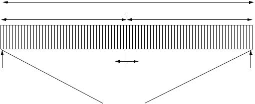
Figure 108—TDD frame structure 8.2.4.2.1 Tx/Rx Transition Gap
The Tx/Rx Transition Gap (TTG) is a gap between the downlink burst and the subsequent uplink burst. This gap allows time for the BS to switch from transmit to receive mode and SSs to switch from receive to transmit mode. During this gap, the BS and SS are not transmitting modulated data but simply allowing the BS transmitter carrier to ramp down, the Tx/Rx antenna switch to actuate, and the BS receiver section to activate. After the gap, the BS receiver shall look for the first symbols of uplink burst. This gap is an integer number of physical slots (PSs) durations and starts on a PS boundary.
8.2.4.2.2 Rx/Tx Transition Gap
The Rx/Tx Transition Gap is a gap between the uplink burst and the subsequent downlink burst. This gap allows time for the BS to switch from receive to transmit mode and SSs to switch from transmit to receive mode. During this gap, the BS and SS are not transmitting modulated data but simply allowing the BS transmitter carrier to ramp up, the Tx/Rx antenna switch to actuate, and the SS receiver sections to activate. After the gap, the SS receivers shall look for the first symbols of QPSK modulated data in the downlink burst. This gap is an integer number of PSs durations and starts on a PS boundary.
8.2.5 Downlink PHY
The available bandwidth in the downlink direction is defined with a granularity of one PS. The available bandwidth in the uplink direction is defined with a granularity of one minislot, where the minislot length is 2m PSs (m ranges from 0 through 7). The number of PSs with each frame is a function of the symbol rate. The symbol rate is selected in order to obtain an integral number of PSs within each frame. For example, with a 20 Mbaud symbol rate, there are 5000 PSs within a 1 ms frame.
8.2.5.1 Downlink subframe
The structure of the downlink subframe using TDD is illustrated in Figure 109. The downlink subframe begins with a Frame Start Preamble used by the PHY for synchronization and equalization. This is followed by the frame control section, containing downlink and uplink maps stating the PSs at which bursts begin. The following TDM portion carries the data, organized into bursts with different burst profiles and therefore
Copyright © 2002 IEEE. All rights reserved. |
219 |

IEEE Std 802.16-2001 |
LOCAL AND METROPOLITAN AREA NETWORKS—PART 16: |
different level of transmission robustness. The bursts are transmitted in order of decreasing robustness. For example, with the use of a single FEC type with fixed parameters, data begins with QPSK modulation, followed by 16-QAM, followed by 64-QAM. In the case of TDD, a TTG separates the downlink subframe from the uplink subframe.
Each SS receives and decodes the control information of the downlink and looks for MAC headers indicating data for that SS in the remainder of the downlink subframe.
Preamble
|
|
|
TDM Portion |
|
|
|
|||
|
|
|
|
|
|
|
|
|
|
|
|
|
|
|
|
|
|
|
|
Broadcast |
TDM |
TDM |
|
TDM |
|
||||
Control |
|
|
|||||||
DIUC = 0 |
DIUC a |
DIUC b |
|
DIUC c |
|
||||
|
|
|
|
|
|
|
|
|
|
Tx/Rx Transition Gap
Preamble
DL-MAP UL-MAP
Figure 109—TDD downlink subframe structure
In the FDD case, the structure of the downlink subframe is illustrated in Figure 110. Like the TDD case, the downlink subframe begins with a Frame Start Preamble followed by a frame control section and a TDM portion organized into bursts transmitted in decreasing order of burst profile robustness. This TDM portion of the downlink subframe contains data transmitted to one or more of the following:
—full-duplex SSs
—half-duplex SSs scheduled to transmit later in the frame than they receive
—half-duplex SSs not scheduled to transmit in this frame.
The FDD downlink subframe continues with a TDMA portion used to transmit data to any half-duplex SSs scheduled to transmit earlier in the frame than they receive. This allows an individual SS to decode a specific portion of the downlink without the need to decode the entire downlink subframe. In the TDMA portion, each burst begins with the Downlink TDMA Burst Preamble for phase resynchronization. Bursts in the TDMA portion need not be ordered by burst profile robustness. The FDD frame control section includes a map of both the TDM and TDMA bursts.
220 |
Copyright © 2002 IEEE. All rights reserved. |

AIR INTERFACE FOR FIXED BROADBAND WIRELESS ACCESS SYSTEMS |
IEEE Std 802.16-2001 |
Preamble
|
|
|
TDM Portion |
|
|
|||
|
|
|
|
|
|
|
|
|
|
|
|
|
|
|
|
|
|
Broadcast |
TDM |
TDM |
|
TDM |
||||
Control |
|
|||||||
DIUC = 0 |
DIUC a |
DIUC b |
|
DIUC c |
||||
|
|
|
|
|
|
|
|
|
|
|
|
|
|
|
|
|
|
TDMA Portion
Preamble
|
|
|
|
|
|
... |
|
Preamble |
DIUC d |
Preamble |
DIUC e |
Preamble |
DIUC f |
Preamble |
|
|
TDMA |
|
TDMA |
|
TDMA |
|
|
|
|
|
|
|
|
|
|
Burst Start Points
DL-MAP UL-MAP
Figure 110—FDD downlink subframe structure
TDMA DIUC g
The TDD downlink subframe, which inherently contains data transmitted to SSs that transmit later in the frame than they receive, is identical in structure to the FDD downlink subframe for a frame in which no halfduplex SSs are scheduled to transmit before they receive.
8.2.5.1.1 Downlink burst preambles
As shown in Table 86, two downlink burst preambles are used. The Frame Start Preamble shall begin each downlink frame. The Downlink TDMA Burst Preamble shall begin each TDMA burst in the TDMA portion of the downlink subframe.
Table 86—Downlink burst preambles
Preamble name |
Burst profile |
Preamble Type |
Modulation Type |
|
|
|
|
Frame Start Preamble |
TDM Burst |
1 |
QPSK |
|
|
|
|
Downlink TDMA Burst Preamble |
TDMA Burst |
2 |
QPSK |
|
|
|
|
Both preambles use QPSK modulation and are based upon +45 degrees rotated constant amplitude zero auto-correlation (CAZAC) sequences (Milewski [B15]). The amplitude of the preamble shall depend on the downlink power adjustment rule (8.2.5.4.7). In the case of the constant peak power scheme (power adjustment rule=0), the preamble shall be transmitted such that its constellation points coincide with the outermost constellation points of the modulation scheme in use. In the case of the constant mean power scheme (power adjustment rule=1), it shall be transmitted with the mean power of the constellation points of the modulation scheme in use.
The Frame Start Preamble (Table 87) consists of a 32-symbol sequence generated by repeating a 16 symbol CAZAC sequence. The Downlink TDMA Burst Preamble (Table 88) consists of a 16 symbol sequence generated by repeating an 8-symbol CAZAC sequence.
Copyright © 2002 IEEE. All rights reserved. |
221 |
IEEE Std 802.16-2001 |
LOCAL AND METROPOLITAN AREA NETWORKS—PART 16: |
Table 87—Frame start preamble
Symbol |
I |
Q |
B(1) |
B(2) |
|
|
|
|
|
1 and 17 |
1 |
1 |
0 |
0 |
|
|
|
|
|
2 and 18 |
–1 |
1 |
1 |
0 |
|
|
|
|
|
3 and 19 |
–1 |
–1 |
1 |
1 |
|
|
|
|
|
4 and 20 |
1 |
–1 |
0 |
1 |
|
|
|
|
|
5 and 21 |
1 |
1 |
0 |
0 |
|
|
|
|
|
6 and 22 |
–1 |
–1 |
1 |
1 |
|
|
|
|
|
7 and 23 |
1 |
1 |
0 |
0 |
|
|
|
|
|
8 and 24 |
–1 |
–1 |
1 |
1 |
|
|
|
|
|
9 and 25 |
1 |
1 |
0 |
0 |
|
|
|
|
|
10 and 26 |
1 |
–1 |
0 |
1 |
|
|
|
|
|
11 and 27 |
–1 |
–1 |
1 |
1 |
|
|
|
|
|
12 and 28 |
–1 |
1 |
1 |
0 |
|
|
|
|
|
13 and 29 |
1 |
1 |
0 |
0 |
|
|
|
|
|
14 and 30 |
1 |
1 |
0 |
0 |
|
|
|
|
|
15 and 31 |
1 |
1 |
0 |
0 |
|
|
|
|
|
16 and 32 |
1 |
1 |
0 |
0 |
|
|
|
|
|
Table 88—Downlink TDMA burst preamble
Symbol |
I |
Q |
B(1) |
B(2) |
|
|
|
|
|
1 and 9 |
1 |
1 |
0 |
0 |
|
|
|
|
|
2 and 10 |
1 |
1 |
0 |
0 |
|
|
|
|
|
3 and 11 |
1 |
1 |
0 |
0 |
|
|
|
|
|
4 and 12 |
–1 |
1 |
1 |
0 |
|
|
|
|
|
5 and 13 |
–1 |
–1 |
1 |
1 |
|
|
|
|
|
6 and 14 |
1 |
1 |
0 |
0 |
|
|
|
|
|
7 and 15 |
–1 |
–1 |
1 |
1 |
|
|
|
|
|
8 and 16 |
–1 |
1 |
1 |
0 |
|
|
|
|
|
222 |
Copyright © 2002 IEEE. All rights reserved. |