

lec11_fsmd
.pdfExample
a a - b + 1
Block diagram
Overview
Finite State Machines (FSMs)
State Graphs: general form
Algorithmic State Machine (ASM) charts
Finite State Machines with Datapath (FSMD)
Algorithmic State Machine with Datapath (ASMD)
11
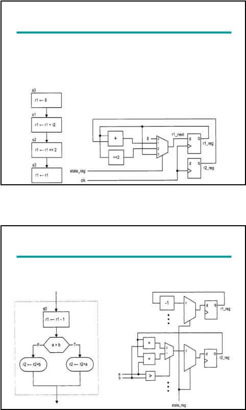
Algorithmic State Machine with Data-path (ASMD)
Extend ASM chart to incorporate RT operations and call it ASMD (ASM with data-path):
ASMD segment |
|
Block diagram: |
|
|
Implementing the RT operations |
|
|
|
Location of RT operation inside ASM block
ASM block |
|
Block diagram |
|
|
|
12
Decision box with a register
RT operation in an ASMD chart is controlled by an embedded clock signal
Destination register is updated when the machine exits the current ASMD block, but not within the block!
Example: r r – 1 means
r_next <= r_reg – 1;
r_reg <= r_next at the rising edge of the clock (when machine exits current block)
Example
Fibonacci number circuit
A sequence of integers
fib(i) = 0, if i = 0 1 if i = 1
fib(i-1) + fib(i-2), if i > 1
13
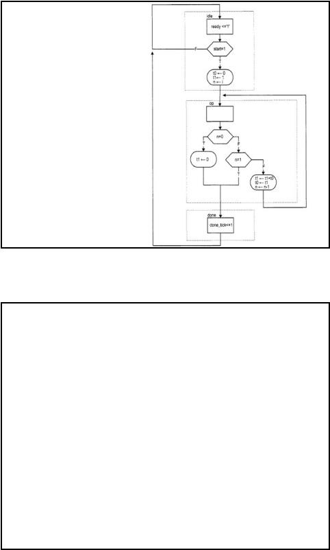
ASMD chart
library ieee;
use ieee.std_logic_1164.all; use ieee.numeric_std.all;
entity fib is port(
clk, reset: in std_logic; start: in std_logic;
i: in std_logic_vector(4 downto 0); ready, done_tick: out std_logic;
f: out std_logic_vector(19 downto 0)
); end fib;
VHDL code
architecture arch of fib is
type state_type is (idle,op,done);
signal state_reg, state_next: state_type;
signal t0_reg, t0_next, t1_reg, t1_next: unsigned(19 downto 0); signal n_reg, n_next: unsigned(4 downto 0);
begin
-- fsmd state and data registers process(clk,reset)
begin
if reset='1' then state_reg <= idle;
t0_reg <= (others=>'0');
t1_reg <= (others=>'0'); n_reg <= (others=>'0');
elsif (clk'event and clk='1') then state_reg <= state_next;
t0_reg <= t0_next;
t1_reg <= t1_next; n_reg <= n_next;
end if; end process;
14
-- fsmd next-state logic process(state_reg,n_reg,t0_reg,t1_reg,start,i,n_next) begin
ready <='0'; done_tick <= '0';
state_next <= state_reg; t0_next <= t0_reg; t1_next <= t1_reg; n_next <= n_reg;
case state_reg is when idle =>
ready <= '1';
if start='1' then
t0_next <= (others=>'0');
t1_next <= (0=>'1', others=>'0'); n_next <= unsigned(i); state_next <= op;
end if; when op =>
if n_reg=0 then
t1_next <= (others=>'0'); state_next <= done;
elsif n_reg=1 then state_next <= done;
else
t1_next <= t1_reg + t0_reg; t0_next <= t1_reg;
n_next <= n_reg - 1; end if;
when done => done_tick <= '1';
state_next <= idle; end case;
end process;
-- output
f <= std_logic_vector(t1_reg); end arch;
Summary
Algorithmic State Machine charts are somewhat more convenient to use to write behavioral VHDL code
Finite State Machines with Datapath (FSMD) and Algorithmic State Machine with Datapath (ASMD) are useful when we care about the internal structure of the circuit (e.g., we want the synthesis tool to preserve the pipeline structure)
15