

lec12_fsmd_2
.pdfEE 459/500 – HDL Based Digital
Design with Programmable Logic
Lecture 12
More on FSMDs
References/credits:
Chapter 6 of: Pong P. Chu, FPGA Prototyping by VHDL Examples: Xilinx Spartan-3 Version, Wiley 2008.
Chapter 5 from textbook.
Overview
Example 1 – period counter
Example 2 – division circuit
Example 3 – binary-2-BCD converter
Example 4 – low-frequency counter
Example 5 – multiplier
1
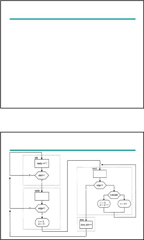
Example 1: Period Counter
Measure the period of a periodic input waveform
One solution: count the number of clock cycles between two rising edges of the input signal
Use a rising-edge detection circuit
Frequency of clock signal is known easy to find the period of input signal: N*1/fCLK
Assume: TCLK = (1/fCLK) = 20 ns
Register t counts for 50,000 clock cycles from 0 to 49,999 then wraps around; it takes 1 ms to circulate through 50,000 cycles
Register p counts in terms of milliseconds
ASMD chart
2

VHDL code
library ieee;
use ieee.std_logic_1164.all; use ieee.numeric_std.all;
entity period_counter is port(
clk, reset: in std_logic; start, si: in std_logic;
ready, done_tick: out std_logic;
prd: out std_logic_vector(9 downto 0)
);
end period_counter;
architecture arch of period_counter is
constant CLK_MS_COUNT: integer := 50000; -- 1 ms tick type state_type is (idle, waite, count, done);
signal state_reg, state_next: state_type;
signal t_reg, t_next: unsigned(15 downto 0); -- up to 50000 signal p_reg, p_next: unsigned(9 downto 0); -- up to 1 sec signal delay_reg: std_logic;
signal edge: std_logic;
begin
--state and data register process(clk,reset)
begin
if reset='1' then state_reg <= idle; t_reg <= (others=>'0'); p_reg <= (others=>'0'); delay_reg <= '0';
elsif (clk'event and clk='1') then state_reg <= state_next;
t_reg <= t_next; p_reg <= p_next; delay_reg <= si;
end if; end process;
--edge detection circuit
edge <= (not delay_reg) and si;
3
-- FSMD next-state logic/DATAPATH operations process(start,edge,state_reg,t_reg,t_next,p_reg)
begin
ready <= '0'; done_tick <= '0';
state_next <= state_reg; p_next <= p_reg;
t_next <= t_reg; case state_reg is when idle =>
ready <= '1';
if (start='1') then state_next <= waite;
end if;
when waite => -- wait for the first edge if (edge='1') then
state_next <= count; t_next <= (others=>'0'); p_next <= (others=>'0');
end if; |
|
when count => |
|
if (edge='1') then |
-- 2nd edge arrived |
state_next <= done; else -- otherwise count
if t_reg = CLK_MS_COUNT-1 then -- 1ms tick t_next <= (others=>'0');
p_next <= p_reg + 1; else
t_next <= t_reg + 1; end if;
end if; when done =>
done_tick <= '1'; state_next <= idle;
end case; end process;
prd <= std_logic_vector(p_reg); end arch;
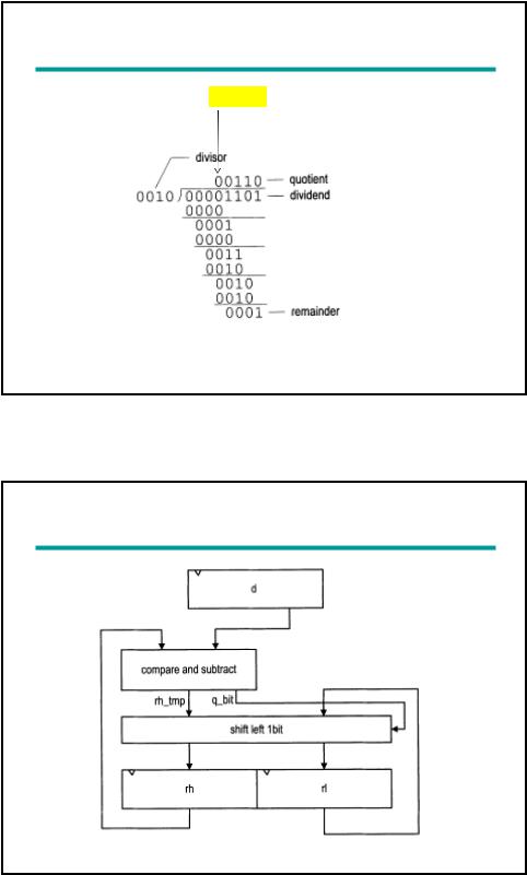
Example 2: Division circuit
Division algorithm of 4-bit unsigned integers:
(1) Double the dividend width by appending 0’s in front and align the divisor to leftmost bit of extended dividend
(2) If corresponding dividend bits are >= to divisor, subtract divisor from dividend and make corresponding quotient bit 1. Otherwise, keep original dividend bits and make quotient bit 0.
(3) Append one additional dividend bit to previous result and shift divisor to right 1 position
(4) Repeat (2) and (3) until all dividend bits are used
4
Division of two 4-bit unsigned integers |
1 2 3 4 5 |
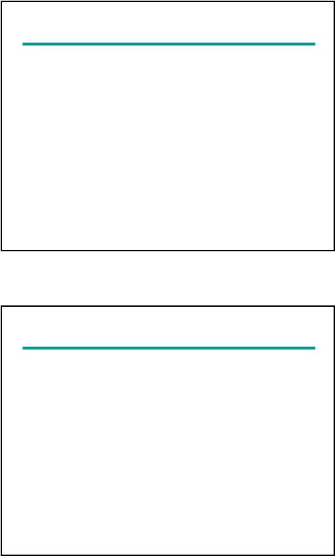
Sketch of Datapath of Division circuit
5

library ieee;
use ieee.std_logic_1164.all; VHDL code use ieee.numeric_std.all;
entity div is generic(
W: integer:=8;
CBIT: integer:=4 -- CBIT=log2(W)+1
);
port(
clk, reset: in std_logic; start: in std_logic;
dvsr, dvnd: in std_logic_vector(W-1 downto 0); ready, done_tick: out std_logic;
quo, rmd: out std_logic_vector(W-1 downto 0)
); end div;
architecture arch of div is
type state_type is (idle,op,last,done); signal state_reg, state_next: state_type;
signal rh_reg, rh_next: unsigned(W-1 downto 0);
signal rl_reg, rl_next: std_logic_vector(W-1 downto 0); signal rh_tmp: unsigned(W-1 downto 0);
signal d_reg, d_next: unsigned(W-1 downto 0); signal n_reg, n_next: unsigned(CBIT-1 downto 0); signal q_bit: std_logic;
begin
-- fsmd state and data registers process(clk,reset)
begin
if reset='1' then state_reg <= idle;
rh_reg <= (others=>'0'); rl_reg <= (others=>'0'); d_reg <= (others=>'0'); n_reg <= (others=>'0');
elsif (clk'event and clk='1') then state_reg <= state_next; rh_reg <= rh_next;
rl_reg <= rl_next; d_reg <= d_next; n_reg <= n_next;
end if; end process;
6

--fsmd next-state logic and data path logic process(state_reg,n_reg,rh_reg,rl_reg,d_reg,
start,dvsr,dvnd,q_bit,rh_tmp,n_next)
begin
ready <='0'; done_tick <= '0';
state_next <= state_reg; rh_next <= rh_reg; rl_next <= rl_reg; d_next <= d_reg;
n_next <= n_reg; case state_reg is when idle =>
ready <= '1';
if start='1' then
rh_next |
<= |
(others=>'0'); |
|
rl_next |
<= |
dvnd; |
-- dividend |
d_next <= unsigned(dvsr); |
-- divisor |
||
n_next <= to_unsigned(W+1, CBIT); -- index |
|||
state_next |
<= op; |
|
|
end if; |
|
|
|
when op => |
|
|
|
-- shift rh and rl left |
|
||
rl_next <= |
rl_reg(W-2 downto 0) & q_bit; |
||
rh_next <= |
rh_tmp(W-2 downto 0) & rl_reg(W-1); |
||
--decrease index |
|
||
n_next <= n_reg - 1; |
|
||
if (n_next=1) |
then |
|
|
state_next |
<= last; |
|
|
end if; |
|
|
|
when last => |
-- |
last iteration |
|
rl_next <= |
rl_reg(W-2 downto 0) & q_bit; |
||
rh_next <= |
rh_tmp; |
|
|
state_next |
<= |
done; |
|
when done => |
|
|
|
state_next |
<= |
idle; |
|
done_tick <= '1'; end case;
end process;
--compare and subtract process(rh_reg, d_reg) begin
if rh_reg >= d_reg then rh_tmp <= rh_reg - d_reg; q_bit <= '1';
else
rh_tmp <= rh_reg; q_bit <= '0';
end if; end process;
--output
quo <= rl_reg;
rmd <= std_logic_vector(rh_reg);
end arch;
7
Example 3: Binary-to-BCD converter
A decimal number is represented as a sequence of 4-bit BCD digits
Example
Binary: 001000000000
BCD: 0101 0001 0010
Decimal: 5 |
1 |
2 |
VHDL description is left as an exercise
Example 3: Entity declaration
entity bin2bcd is port(
clk: in std_logic; reset: in std_logic; start: in std_logic;
bin: in std_logic_vector(12 downto 0); ready, done_tick: out std_logic;
bcd3,bcd2,bcd1,bcd0: out std_logic_vector(3 downto 0)
);
end bin2bcd ;
8
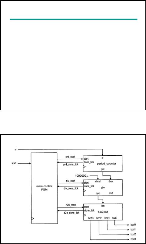
Example 4: Accurate low-frequency counter
Measure frequency of a periodic input waveform
One way:
Count number of input pulses in a fixed amount of time, say 1 sec
Not working for low-frequency signals; example 2 Hz
Another way:
(1) Measure period of signal, (2) Take reciprocal (f=1/T), (3) Convert binary number to BCD format
Assume: frequency of input signal is between 1-10 Hz (T = 100...1000 ms)
Structural description: Instantiate a period counter, a division circuit, and a binary-3-BCD converter
Block diagram
9
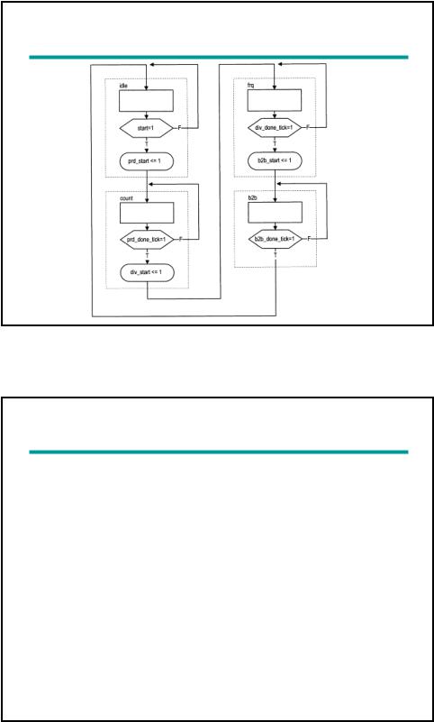
ASM chart of main control
VHDL code
library ieee;
use ieee.std_logic_1164.all; use ieee.numeric_std.all;
entity low_freq_counter is port(
clk, reset: in std_logic; start: in std_logic;
si: in std_logic;
bcd3, bcd2, bcd1, bcd0: out std_logic_vector(3 downto 0)
);
end low_freq_counter;
architecture arch of low_freq_counter is
type state_type is (idle, count, frq, b2b); signal state_reg, state_next: state_type; signal prd: std_logic_vector(9 downto 0);
signal dvsr, dvnd, quo: std_logic_vector(19 downto 0); signal prd_start, div_start, b2b_start: std_logic;
signal prd_done_tick, div_done_tick, b2b_done_tick: std_logic;
begin
10