


Activity 2.2.5: Using NeoTrace™ to View Internetworks
Learning Objectives
•Explain the use of route tracing programs, such as tracert and NeoTrace.
•Use tracert and NeoTrace to trace a route from its PC to a distant server.
•Describe the interconnected and global nature of the Internet with respect to data flow.
Background
Route tracing computer software is a utility that lists the networks data has to traverse from the user's originating end device to a distant destination network.
This network tool is typically executed at the command line as:
traceroute <destination network name or end device address>
(Unix and similar systems)
or
tracert <destination network name or end device address>
(MS Windows systems)
and determines the route taken by packets across an IP network.
The traceroute (or tracert) tool is often used for network troubleshooting. By showing a list of routers traversed, it allows the user to identify the path taken to reach a particular destination on the network or across internetworks. Each router represents a point where one network connects to another network and the packet was forwarded through. The number of routers is known as the number of "hops" the data traveled from source to destination.
The displayed list can help identify data flow problems when trying to access a service such as a website. It can also be useful when performing tasks such as downloading data. If there are multiple websites (mirrors) available for the same file of data, one can trace each mirror to get a good idea of which mirror would be the fastest to use.
However, it should be noted that because of the "meshed" nature of the interconnected networks that make up the Internet and the Internet Protocol's ability to select different pathways over which to send packets, two trace routes between the same source and destination conducted some time apart may produce different results.
Tools such as these are usually embedded with the operating system of the end device.
Others such as NeoTrace™ are proprietary programs that provide extra information. NeoTrace uses available online information to display graphically the route traced on a global map, for example.
Scenario
Using an Internet connection, you will use two routing tracing programs to examine the Internet pathway to destination networks.
This activity should be preformed on a computer that has Internet access and access to a command line. First, you will use the Windows embedded tracert utility and then the more enhanced NeoTrace program. This lab assumes the installation of NeoTrace.
All contents are Copyright © 1992–2007 Cisco Systems, Inc. All rights reserved. This document is Cisco Public Information. |
Page 1 of 3 |
CCNA Exploration |
|
Network Fundamentals: |
|
Communicating over the Network |
Activity 2.2.5: Using NeoTrace™ to View Internetworks |
Task 1: Trace Route to Remote Server.
Step 1: Trace the route to a distant network.
To trace the route to a distant network, the PC being used must have a working connection to the class/lab network.
1.At the command line prompt, type: tracert www.cisco.com
The first output line should show the Fully Qualified Domain Name (FQDN) followed by the IP address. The Lab Domain Name Service (DNS) server was able to resolve the name to an IP address. Without this name resolution, the tracert would have failed, because this tool operates at the TCP/IP layers that only understand valid IP addresses.
If DNS is not available, the IP address of the destination device has to be entered after the tracert command instead of the server name.
2.Examine the output displayed.
How many hops between the source and destination? ________
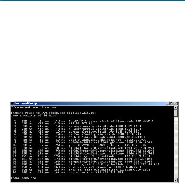
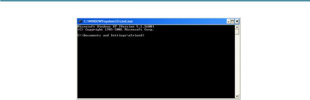
Figure 1. tracert Command
Figure 1 shows the successful result when running:
tracert www.cisco.com
from a location in Bavaria, Germany.
The first output line shows the FQDN, followed by the IP address. Therefore, a DNS server was able to resolve the name to an IP address. Then there are listings of all routers through which the tracert requests had to pass to get to the destination.
3.Try the same trace route on a PC connected to the Internet, and examine your output. Number of hops to www.cisco.com: ___________
Step 2: Try another trace route on the same PC, and examine your output.
Destination URL: __________________________________________
Destination IP Address: _____________________________________
All contents are Copyright © 1992–2007 Cisco Systems, Inc. All rights reserved. This document is Cisco Public Information. |
Page 2 of 3 |
CCNA Exploration |
|
Network Fundamentals: |
|
Communicating over the Network |
Activity 2.2.5: Using NeoTrace™ to View Internetworks |
Task 2: Trace Route using NeoTrace.
1.Launch the NeoTrace program.
2.On the View menu, choose Options. Click the Map tab and in the Home Location section click the Set Home Location button.
3.Follow the instructions to select your country and location in your country.
Alternatively, you can click the Advanced button, which enables you to enter the precise latitude and longitude of your location. See the Challenge section of Activity 1.2.5(1).
4.Enter “www.cisco.com” in the Target field and click Go.
5.From the View menu, List View displays the list of routers similar to tracert.
Node View from the View menu displays the connections graphically with symbols.
Map View on the View menu displays the links and routers in their geographic location on a global map.
6.Select each view in turn and note the differences and similarities.
7.Try a number of different URLs and view the routes to those destinations.
Task 3: Reflection
Review the purpose and usefulness of trace route programs.
Relate the displays of the output of NeoTrace to the concept of interconnected networks and the global nature of the Internet.
Task 4: Challenge
Consider and discuss possible network security issues that could arise from the use of programs like traceroute and NeoTrace. Consider what technical details are revealed and how perhaps this information could be misused.
Task 5: Clean Up
Exit the NeoTrace program.
Unless instructed otherwise by your instructor, properly shut down the computer.
All contents are Copyright © 1992–2007 Cisco Systems, Inc. All rights reserved. This document is Cisco Public Information. |
Page 3 of 3 |
Lab 2.6.1: Topology Orientation and Building a Small Network
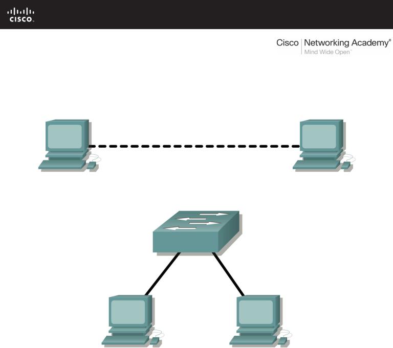
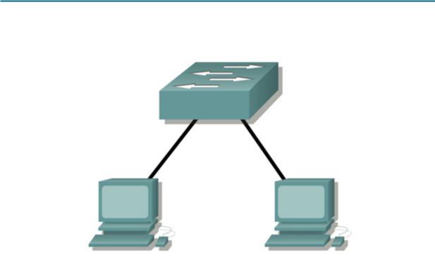
Topology Diagram
Peer to Peer Network
Switched Network
Learning Objectives
Upon completion of this lab, you will be able to:
•Correctly identify cables for use in the network.
•Physically cable a peer-to-peer and switched network.
•Verify basic connectivity on each network.
Background
Many network problems can be fixed at the Physical layer of a network. For this reason, it is important to have a clear understanding of which cables to use for your network connections.
At the Physical layer (Layer 1) of the OSI model, end devices must be connected by media (cables). The type of media required depends on the type of device being connected. In the basic portion of this lab, straight–through or patch—cables will be used to connect workstations and switches.
All contents are Copyright © 1992–2007 Cisco Systems, Inc. All rights reserved. This document is Cisco Public Information. |
Page 1 of 7 |

CCNA Exploration |
|
Network Fundamentals: |
|
Communicating over the Network |
Lab 2.6.1: Topology Orientation and Building a Small Network |
In addition, two or more devices communicate through an address. The Network layer (Layer 3) requires a unique address (also know as a logical address or IP Addresses), which allows the data to reach the appropriate destination device.
Addressing for this lab will be applied to the workstations and will be used to enable communication between the devices.
Scenario
This lab starts with the simplest form of networking (peer-to-peer) and ends with the lab connecting through a switch.
Task 1: Create a Peer-to-Peer Network.
Step 1: Select a lab partner.
Step 2: Obtain equipment and resources for the lab.
Equipment needed:
2workstations
2straight through (patch) cables 1 crossover cable
1 switch (or hub)
Task 2: Identify the Cables used in a Network.
Before the devices can be cabled, you will need to identify the types of media you will be using. The cables used in this lab are crossover and straight-through.
Use a crossover cable to connect two workstations to each other through their NIC’s Ethernet port. This is an Ethernet cable. When you look at the plug you will notice that the orange and green wires are in opposite positions on each end of the cable.
Use a straight-through cable to connect the router’s Ethernet port to a switch port or a workstation to a switch port. This is also an Ethernet cable. When you look at the plug you will notice that both ends of the cable are exactly the same in each pin position.
Task 3: Cable the Peer-to-peer Network.
Step 1: Connect two workstations.
Using the correct Ethernet cable, connect two workstations together. Connect one end of the cable to the NIC port on PC1 and the other end of the cable to PC2.
Which cable did you use? _______________________________
All contents are Copyright © 1992–2007 Cisco Systems, Inc. All rights reserved. This document is Cisco Public Information. |
Page 2 of 7 |
CCNA Exploration |
|
Network Fundamentals: |
|
Communicating over the Network |
Lab 2.6.1: Topology Orientation and Building a Small Network |
Step 2: Apply a Layer 3 address to the workstations.
To complete this task, you will need to follow the step-by-step instructions below.
Note: These steps must be completed on each workstation. The instructions are for Windows XP—steps may differ slightly if you are using a different operating system.
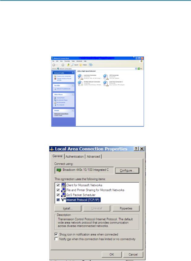
1.On your computer, click Start, right-click My Network Places, and then click Properties. The Network Connections window should appear, with icons showing the different network connections.
2.Right-click the Local Area Connection and click Properties.
3.Select the Internet Protocol (TCP/IP) item and then click the Properties button.
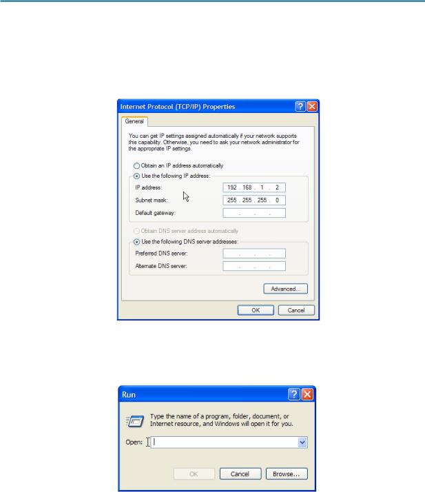
4.On the General tab of the Internet Protocol (TCP/IP) Properties window, select the Use the following IP address option.
All contents are Copyright © 1992–2007 Cisco Systems, Inc. All rights reserved. This document is Cisco Public Information. |
Page 3 of 7 |
CCNA Exploration |
|
Network Fundamentals: |
|
Communicating over the Network |
Lab 2.6.1: Topology Orientation and Building a Small Network |
5.In the IP address box, enter the IP address 192.168.1.2 for PC1. (Enter the IP address 192.168.1.3 for PC2.)
6.Press the tab key and the Subnet mask is automatically entered. The subnet address should be 255.255.255.0. If this address is not automatically entered, enter this address manually.
7.Click OK.
8. Close the Local Area Connection Properties window.
Step 3: Verify connectivity.
1. On your computer, click Start, and then click Run.
2.Type cmd in the Open box and then click OK.
The DOS command (cmd.exe) window will appear. You can enter DOS commands using this window. For the purposes of this lab, basic network commands will be entered to allow you to test you computer connections.
All contents are Copyright © 1992–2007 Cisco Systems, Inc. All rights reserved. This document is Cisco Public Information. |
Page 4 of 7 |
CCNA Exploration |
|
Network Fundamentals: |
|
Communicating over the Network |
Lab 2.6.1: Topology Orientation and Building a Small Network |
The ping command is a computer network tool used to test whether a host (workstation, router, server, etc.) is reachable across an IP network.
3.Use the ping command to verify that PC1 can reach PC2 and PC2 can reach PC1. From the PC1 DOS command prompt, type ping 192.168.1.3. From the PC2 DOS command prompt, type ping 192.168.1.2.
What is the output of the ping command?
______________________________________________________________
______________________________________________________________
______________________________________________________________
______________________________________________________________
If the ping command displays an error message or doesn’t receive a reply from the other workstation, troubleshoot as necessary. Possible areas to troubleshoot include:
•Verifying the correct IP addresses on both workstations
•Ensuring that the correct type of cable is used between the workstations
What is the output of the ping command if you unplug the network cable and ping the other workstation?
______________________________________________________________
______________________________________________________________
______________________________________________________________
______________________________________________________________
All contents are Copyright © 1992–2007 Cisco Systems, Inc. All rights reserved. This document is Cisco Public Information. |
Page 5 of 7 |
CCNA Exploration |
|
Network Fundamentals: |
|
Communicating over the Network |
Lab 2.6.1: Topology Orientation and Building a Small Network |
Task 4: Connect Your Workstations to the Classroom Lab Switch.
Step 1: Connect workstation to switch.
Using the correct cable, connect one end of the cable to the NIC port on the workstation and the other end to a port on the switch.
Step 2: Repeat this process for each workstation on your network.
Which cable did you use? ______________________________
Step 3: Verify connectivity.
Verify network connectivity by using the ping command to reach the other workstations attached to the switch.
What is the output of the ping command?
______________________________________________________________
______________________________________________________________
______________________________________________________________
______________________________________________________________
What is the output of the ping command if you ping an address that is not connected to this network?
______________________________________________________________
______________________________________________________________
______________________________________________________________
______________________________________________________________
Step 4: Share a document between PCs.
1.On your desktop, create a new folder and name it test.
2.Right-click the folder and click File sharing. Note: A hand will be placed under the icon.
All contents are Copyright © 1992–2007 Cisco Systems, Inc. All rights reserved. This document is Cisco Public Information. |
Page 6 of 7 |

CCNA Exploration |
|
Network Fundamentals: |
|
Communicating over the Network |
Lab 2.6.1: Topology Orientation and Building a Small Network |
3.Place a file in the folder.
4.On the desktop, double-click My Network Places and then Computers Near Me.
5.Double-click the workstation icon. The test folder should appear. You will be able to access this folder across the network. Once you are able to see it and work with the file, you have access through all 7 layers of the OSI model.
Task 5: Reflection
What could prevent a ping from being sent between the workstations when they are directly connected?
___________________________________________________________________________________
___________________________________________________________________________________
___________________________________________________________________________________
___________________________________________________________________________________
What could prevent the ping from being sent to the workstations when they are connected through the switch?
___________________________________________________________________________________
___________________________________________________________________________________
___________________________________________________________________________________
___________________________________________________________________________________
All contents are Copyright © 1992–2007 Cisco Systems, Inc. All rights reserved. This document is Cisco Public Information. |
Page 7 of 7 |