

Lab 6.7.2: Examining ICMP Packets
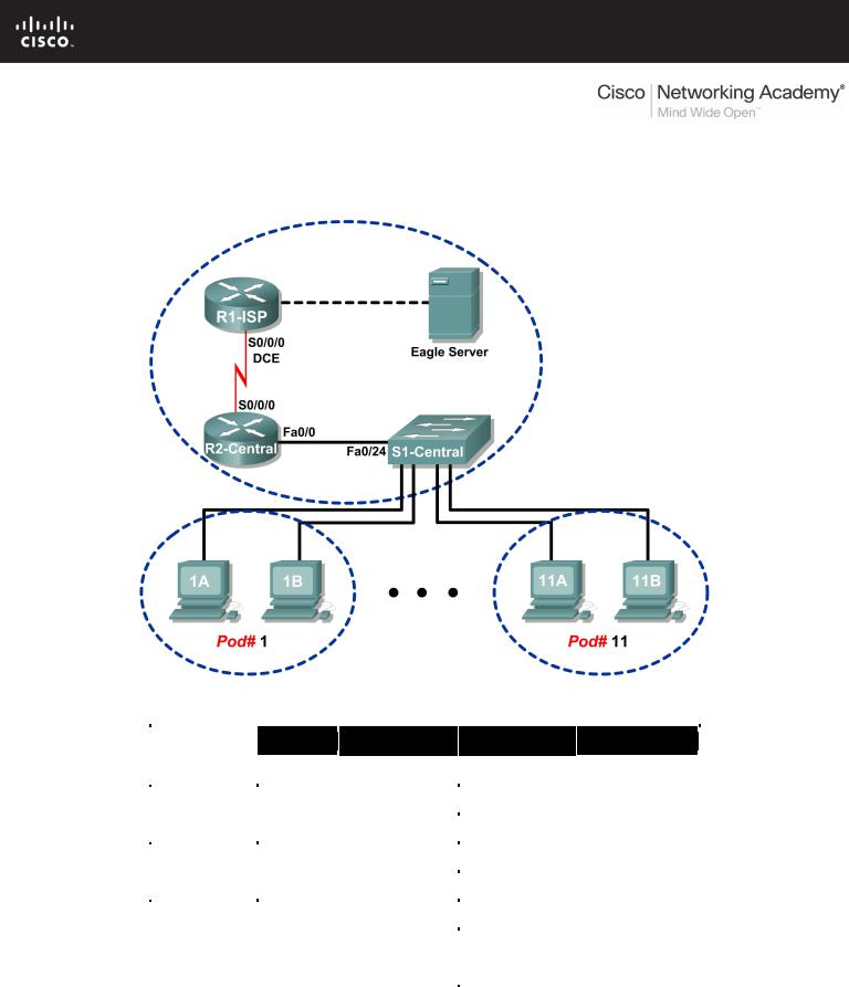
Topology Diagram
Addressing Table
Device |
Interface |
IP Address |
Subnet Mask |
Default Gateway |
|
|
|
|
|
|
|
R1-ISP |
S0/0/0 |
10.10.10.6 |
255.255.255.252 |
N/A |
|
|
|
|
|
||
Fa0/0 |
192.168.254.253 |
255.255.255.0 |
N/A |
||
|
|||||
|
|
|
|
|
|
R2-Central |
S0/0/0 |
10.10.10.5 |
255.255.255.252 |
10.10.10.6 |
|
|
|
|
|
||
Fa0/0 |
172.16.255.254 |
255.255.0.0 |
N/A |
||
|
|||||
|
|
|
|
|
|
|
N/A |
192.168.254.254 |
255.255.255.0 |
192.168.254.253 |
|
Eagle Server |
|
||||
|
|
|
|
||
N/A |
172.31.24.254 |
255.255.255.0 |
N/A |
||
|
|||||
|
|
||||
|
|
|
|
|
|
hostPod#A |
N/A |
172.16.Pod#.1 |
255.255.0.0 |
172.16.255.254 |
|
|
|||||
|
|
|
|
|
|
hostPod#B |
N/A |
172.16.Pod#.2 |
255.255.0.0 |
172.16.255.254 |
|
|
|||||
|
|
|
|
|
|
S1-Central |
N/A |
172.16.254.1 |
255.255.0.0 |
172.16.255.254 |
|
|
|||||
|
|
|
|
|
All contents are Copyright © 1992–2007 Cisco Systems, Inc. All rights reserved. This document is Cisco Public Information. |
Page 1 of 8 |
CCNA Exploration |
|
Network Fundamentals: Addressing the Network - IPV4 |
Lab 6.7.2: Examining ICMP Packets |
Learning Objectives
Upon completion of this lab, you will be able to:
•Understand the format of ICMP packets.
•Use Wireshark to capture and examine ICMP messages.
Background
The Internet Control Message Protocol (ICMP) was first defined in RFC 792, September, 1981. ICMP message types were later expanded in RFC 1700. ICMP operates at the TCP/IP Network layer and is used to exchange information between devices.
ICMP packets serve many uses in today’s computer network. When a router cannot deliver a packet to a destination network or host, an informational message is returned to the source. Also, the ping and tracert commands send ICMP messages to destinations, and destinations respond with ICMP messages.
Scenario
Using the Eagle 1 Lab, Wireshark captures will be made of ICMP packets between network devices.
Task 1: Understand the Format of ICMP Packets.
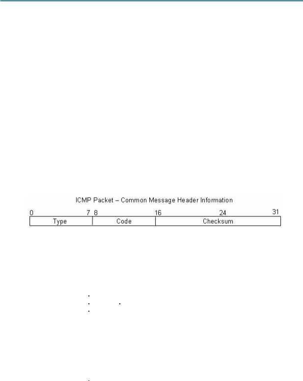
Figure 1. ICMP Message Header
Refer to Figure 1, the ICMP header fields common to all ICMP message types. Each ICMP message starts with an 8-bit Type field, an 8-bit Code field, and a computed 16-bit Checksum. The ICMP message type describes the remaining ICMP fields. The table in Figure 2 shows ICMP message types from RFC 792:
Value |
Meaning |
0 |
Echo Reply |
|
|
3 |
Destination Unreachable |
4 |
Source Quench |
5 |
Redirect |
|
|
8 |
Echo |
11 |
Time Exceeded |
12 |
Parameter Problem |
13 |
Timestamp |
|
|
14 |
Timestamp Reply |
15 |
Information Request |
16 |
Information Reply |
Figure 2. ICMP Message Types
Codes provide additional information to the Type field. For example, if the Type field is 3, destination unreachable, additional information about the problem is returned in the Code field. The table in Figure 3 shows message codes for an ICMP Type 3 message, destination unreachable, from RFC 1700:
All contents are Copyright © 1992–2007 Cisco Systems, Inc. All rights reserved. This document is Cisco Public Information. |
Page 2 of 8 |
CCNA Exploration |
|
Network Fundamentals: Addressing the Network - IPV4 |
Lab 6.7.2: Examining ICMP Packets |
Code |
|
|
Value |
|
Meaning |
0 |
Net Unreachable |
|
1 |
Host Unreachable |
|
2 |
Protocol Unreachable |
|
|
|
|
3 |
Port Unreachable |
|
4 |
Fragmentation Needed and Don't Fragment was Set |
|
5 |
Source Route Failed |
|
|
|
|
6 |
Destination Network Unknown |
|
7 |
Destination Host |
Unknown |
8 |
Source Host Isolated |
|
9 |
Communication with Destination Network is |
|
|
Administratively |
Prohibited |
10 |
Communication with Destination Host is |
|
|
Administratively |
Prohibited |
11 |
Destination Network Unreachable for Type of Service |
|
|
|
|
12 |
Destination Host |
Unreachable for Type of Service |
Figure 3. ICMP Type 3 Message Codes
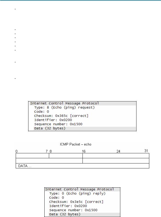
Using ICMP message capture shown in Figure 4, fill in the fields for the ICMP packet echo request. Values beginning with 0x are hexadecimal numbers:
Figure 4. ICMP Packet Echo Request
Using the ICMP message capture shown in Figure 5, fill in the fields for the ICMP packet echo reply:
Figure 5. ICMP Packet Echo Reply
All contents are Copyright © 1992–2007 Cisco Systems, Inc. All rights reserved. This document is Cisco Public Information. |
Page 3 of 8 |
CCNA Exploration |
|
Network Fundamentals: Addressing the Network - IPV4 |
Lab 6.7.2: Examining ICMP Packets |
At the TCP/IP Network layer, communication between devices is not guaranteed. However, ICMP does provide minimal checks for a reply to match the request. From the information provided in the ICMP messages above, how does the sender know that the reply is to a specific echo?
___________________________________________________________________________________
___________________________________________________________________________________
Task 2: Use Wireshark to Capture and Examine ICMP Messages.
Figure 6. Wireshark Download Site
If Wireshark has not been loaded on the pod host computer, it can be downloaded from Eagle Server.
1.Open a web browser, URL FTP://eagleserver.example.com/pub/eagle_labs/eagle1/chapter6, as shown in Figure 6.
2.Right-click the Wireshark filename, click Save Link As, and save the file to the pod host computer.
3.When the file has been downloaded, open and install Wireshark.
Step 1: Capture and evaluate ICMP echo messages to Eagle Server.
In this step, Wireshark will be used to examine ICMP echo messages.
1.Open a Windows terminal on the pod host computer.
2.When ready, start Wireshark capture.
All contents are Copyright © 1992–2007 Cisco Systems, Inc. All rights reserved. This document is Cisco Public Information. |
Page 4 of 8 |
CCNA Exploration |
|
Network Fundamentals: Addressing the Network - IPV4 |
Lab 6.7.2: Examining ICMP Packets |
C:\> ping eagle-server.example.com
Pinging eagle-server.example.com [192.168.254.254] with 32 bytes of data:
Reply from 192.168.254.254: bytes=32 time<1ms TTL=63 Reply from 192.168.254.254: bytes=32 time<1ms TTL=63 Reply from 192.168.254.254: bytes=32 time<1ms TTL=63 Reply from 192.168.254.254: bytes=32 time<1ms TTL=63 Ping statistics for 192.168.254.254:
Packets: Sent = 4, Received = 4, Lost = 0 (0% loss), Approximate round trip times in milli-seconds:
Minimum = 0ms, Maximum = 0ms, Average = 0ms
C:\>
Figure 7. Successful ping Replies from Eagle Server
3.From the Windows terminal, ping Eagle Server. Four successful replies should be received from Eagle Server, as shown in Figure 7.
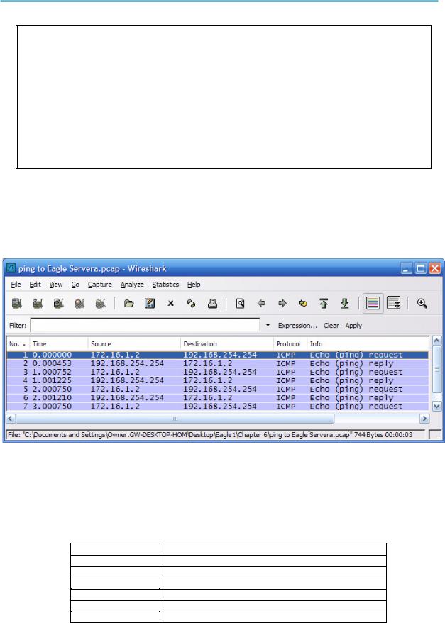
4.Stop Wireshark capture. There should be a total of four ICMP echo requests and matching echo replies, similar to those shown in Figure 8.
Figure 8. Wireshark Capture of ping Requests and Replies
Which network device responds to the ICMP echo request? __________________________________
5.Expand the middle window in Wireshark, and expand the Internet Control Message Protocol record until all fields are visible. The bottom window will also be needed to examine the Data field.
6.Record information from the first echo request packet to Eagle Server:
Field |
Value |
Type
Code
Checksum
Identifier
Sequence number
Data
All contents are Copyright © 1992–2007 Cisco Systems, Inc. All rights reserved. This document is Cisco Public Information. |
Page 5 of 8 |

CCNA Exploration |
|
Network Fundamentals: Addressing the Network - IPV4 |
Lab 6.7.2: Examining ICMP Packets |
Are there 32 bytes of data? _____
7. Record information from the first echo reply packet from Eagle Server:
Field |
Value |
Type
Code
Checksum
Identifier
Sequence number
Data
Which fields, if any, changed from the echo request?
___________________________________________________________________________________
8.Continue to evaluate the remaining echo requests and replies. Fill in the following information from each new ping:
Packet |
Checksum |
Identifier |
Sequence number |
Request # 2 |
|
|
|
Reply # 2 |
|
|
|
Request # 3 |
|
|
|
Reply # 3 |
|
|
|
Request # 4 |
|
|
|
Reply # 4 |
|
|
|
Why did the Checksum values change with each new request?
___________________________________________________________________________________
Step 2: Capture and evaluate ICMP echo messages to 192.168.253.1.
In this step, pings will be sent to a fictitious network and host. The results from the Wireshark capture will be evaluated—and may be surprising.
Try to ping IP address 192.168.253.1.
C:\> ping 192.168.253.1
C:\> ping 192.168.253.1
Pinging 192.168.253.1 with 32 bytes of data:
Reply from 172.16.255.254: Destination host unreachable.
Reply from 172.16.255.254: Destination host unreachable.
Reply from 172.16.255.254: Destination host unreachable.
Reply from 172.16.255.254: Destination host unreachable.
Ping statistics for 192.168.253.1:
Packets: Sent = 4, Received = 4, Lost = 0 (0% loss),
Approximate round trip times in milli-seconds:
Minimum = 0ms, Maximum = 0ms, Average = 0ms
C:\>
Figure 9. Ping Results from a Fictitious Destination
See Figure 9. Instead of a request timeout, there is an echo response.
All contents are Copyright © 1992–2007 Cisco Systems, Inc. All rights reserved. This document is Cisco Public Information. |
Page 6 of 8 |
CCNA Exploration |
|
Network Fundamentals: Addressing the Network - IPV4 |
Lab 6.7.2: Examining ICMP Packets |
What network device responds to pings to a fictitious destination?
___________________________________________________________________________________
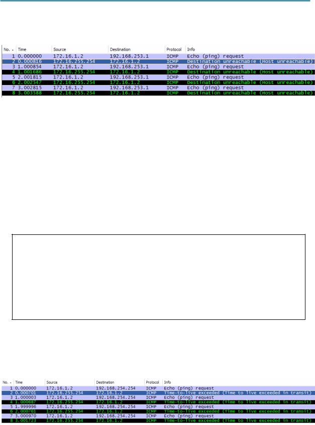
Figure 10. Wireshark Capture from a Fictitious Destination
Wireshark captures to a fictitious destination are shown in Figure 10. Expand the middle Wireshark window and the Internet Control Message Protocol record.
Which ICMP message type is used to return information to the sender?
___________________________________________________________________________________
What is the code associated with the message type?
___________________________________________________________________________________
Step 3: Capture and evaluate ICMP echo messages that exceed the TTL value.
In this step, pings will be sent with a low TTL value, simulating a destination that is unreachable. Ping Eagle Server, and set the TTL value to 1:
C:\> ping -i 1 192.168.254.254
C:\> ping -i 1 192.168.254.254
Pinging 192.168.254.254 with 32 bytes of data:
Reply from 172.16.255.254: TTL expired in |
transit. |
|
|
Reply from 172.16.255.254: TTL expired in |
transit. |
|
|
Reply from 172.16.255.254: TTL expired in |
transit. |
|
|
Reply from 172.16.255.254: TTL expired in |
transit. |
|
|
Ping statistics for 192.168.254.254: |
|
|
|
|
|
|
|
|
Packets: Sent = 4, Received = 4, Lost |
= 0 (0% loss), |
|
Approximate round trip times in milli-seconds: |
|||
|
Minimum = 0ms, Maximum = 0ms, Average |
= 0ms |
|
C:\> |
|
|
|
Figure 11. Ping Results for an Exceeded TTL
See Figure 11, which shows ping replies when the TTL value has been exceeded. What network device responds to pings that exceed the TTL value?
___________________________________________________________________________________
Figure 12. Wireshark Capture of TTL Value Exceeded
All contents are Copyright © 1992–2007 Cisco Systems, Inc. All rights reserved. This document is Cisco Public Information. |
Page 7 of 8 |

CCNA Exploration |
|
Network Fundamentals: Addressing the Network - IPV4 |
Lab 6.7.2: Examining ICMP Packets |
Wireshark captures to a fictitious destination are shown in Figure 12. Expand the middle Wireshark window and the Internet Control Message Protocol record.
Which ICMP message type is used to return information to the sender?
___________________________________________________________________________________
What is the code associated with the message type?
___________________________________________________________________________________
Which network device is responsible for decrementing the TTL value?
___________________________________________________________________________________
Task 3: Challenge
Use Wireshark to capture a tracert session to Eagle Server and then to 192.168.254.251. Examine the ICMP TTL exceeded message. This will demonstrate how the tracert command traces the network path to the destination.
Task 4: Reflection
The ICMP protocol is very useful when troubleshooting network connectivity issues. Without ICMP messages, a sender has no way to tell why a destination connection failed. Using the ping command, different ICMP message type values were captured and evaluated.
Task 5: Clean Up
Wireshark may have been loaded on the pod host computer. If the program must be removed, click Start > Control Panel > Add or Remove Programs, and scroll down to Wireshark. Click the filename, click Remove, and follow uninstall instructions.
Remove any Wireshark pcap files that were created on the pod host computer.
Unless directed otherwise by the instructor, turn off power to the host computers. Remove anything that was brought into the lab, and leave the room ready for the next class.
All contents are Copyright © 1992–2007 Cisco Systems, Inc. All rights reserved. This document is Cisco Public Information. |
Page 8 of 8 |