

Lab 11.5.3: Configure Host Computers for IP Networking
Topology Diagram
Learning Objectives
Upon completion of this lab, you will be able to:
•Design the logical lab topology.
•Configure the physical lab topology.
•Configure the logical LAN topology.
•Verify LAN connectivity.
Background
Hardware |
Qty |
Description |
|
|
|
Cisco Router |
1 |
Part of CCNA Lab |
|
|
bundle |
Cisco Switch |
1 |
Part of CCNA Lab |
|
|
bundle |
*Computer (Host) |
3 |
Lab computer |
CAT-5 or better straight-through UTP cables |
3 |
Connects Router1 |
|
|
and computers Host1 |
|
|
and Host2 to switch1 |
Table 1. Equipment and Hardware for this Lab
Gather the necessary equipment and cables. To configure the lab, make sure the equipment listed in Table 1 is available.
All contents are Copyright © 1992–2007 Cisco Systems, Inc. All rights reserved. This document is Cisco Public Information. |
Page 1 of 8 |

CCNA Exploration |
|
Network Fundamentals: |
|
Configuring and Testing Your Network |
Lab 11.5.3 Configure Host Computers for IP Networking |
Scenario
In this lab students will create a small network that requires connecting network devices and configuring host computers for basic network connectivity. The Appendix is a reference for configuring the logical network.
Task 1: Design the Logical Lab Topology.
1.Given an IP address of 192.168.254.0/24, and 5 bits used for subnets, fill in the following information:
Maximum number of usable subnets (including the 0th subnet): __________
Number of usable Hosts per subnet: __________
|
IP Address: 192.168.254.0 |
Subnet mask: |
||
|
|
|
|
|
# |
Subnet |
First Host address |
Last Host address |
Broadcast |
|
|
|
|
|
0 |
|
|
|
|
1 |
|
|
|
|
2 |
|
|
|
|
3 |
|
|
|
|
4 |
|
|
|
|
5 |
|
|
|
|
6 |
|
|
|
|
7 |
|
|
|
|
8 |
|
|
|
|
9 |
|
|
|
|
10 |
|
|
|
|
11 |
|
|
|
|
12 |
|
|
|
|
13 |
|
|
|
|
14 |
|
|
|
|
15 |
|
|
|
|
16 |
|
|
|
|
17 |
|
|
|
|
18 |
|
|
|
|
19 |
|
|
|
|
20 |
|
|
|
|
21 |
|
|
|
|
22 |
|
|
|
|
23 |
|
|
|
|
24 |
|
|
|
|
25 |
|
|
|
|
26 |
|
|
|
|
27 |
|
|
|
|
28 |
|
|
|
|
29 |
|
|
|
|
30 |
|
|
|
|
2.Before proceeding, verify your addresses with the instructor. The instructor will assign one subnetwork per student or team.
All contents are Copyright © 1992–2007 Cisco Systems, Inc. All rights reserved. This document is Cisco Public Information. |
Page 2 of 8 |
CCNA Exploration |
|
Network Fundamentals: |
|
Configuring and Testing Your Network |
Lab 11.5.3 Configure Host Computers for IP Networking |
Task 2: Configure the Physical Lab Topology.
Step 1: Physically connect devices.
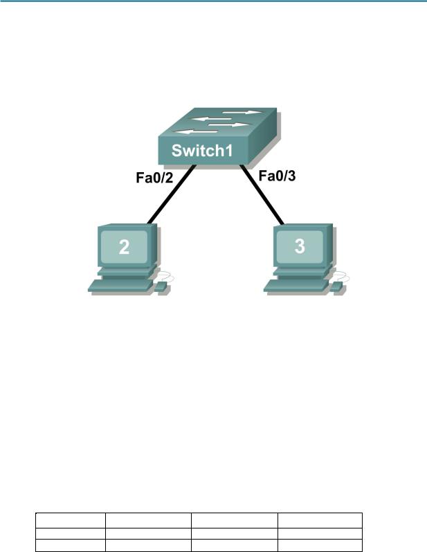
1. Cable the network devices as shown in Figure 1.
Figure 1. Cabling the Network
Is a crossover cable needed to connect Host computers to the switch? Why or why not?
_____________________________________________________________________________
_____________________________________________________________________________
If not already enabled, turn power on to all devices.
Step 2: Visually inspect network connections.
After cabling the network devices, take a moment to verify the connections. Attention to detail now will minimize the time required to troubleshoot network connectivity issues later.
Task 3: Configure the Logical Topology.
Step 1: Document logical network settings.
1.Host computers will use the first two IP addresses in the subnetwork. Write down the IP address information for each device:
Device |
Subnetwork |
IP address |
Mask |
Host1
Host2
Figure 2. Logical Topology
All contents are Copyright © 1992–2007 Cisco Systems, Inc. All rights reserved. This document is Cisco Public Information. |
Page 3 of 8 |
CCNA Exploration |
|
Network Fundamentals: |
|
Configuring and Testing Your Network |
Lab 11.5.3 Configure Host Computers for IP Networking |
2. From the information given in Figure 2, write down the IP network addressing for each computer:
Host 1
IP Address
IP Mask
Host 2
IP Address
IP Mask
Step 2: Configure Host1 computer.
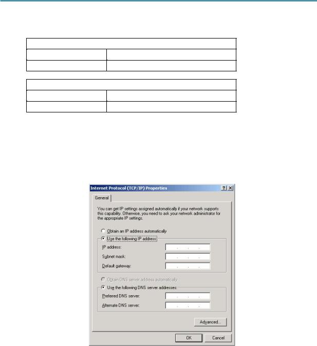
1.On Computer1, click Start > Control Panel > Network Connections. Right-click the LAN icon, and choose Properties. On the General tab, select Internet Protocol (TCP/IP), and then click the Properties button.
Figure 3. Host1 IP Address and Gateway Settings
2.Refer to Figure 3 for Host1 IP address and gateway settings.
3.When finished, click OK, then click Close. The computer may require a reboot for changes to be effective.
4.Verify proper configuration of Host1 with the ipconfig /all command.
All contents are Copyright © 1992–2007 Cisco Systems, Inc. All rights reserved. This document is Cisco Public Information. |
Page 4 of 8 |
CCNA Exploration |
|
Network Fundamentals: |
|
Configuring and Testing Your Network |
Lab 11.5.3 Configure Host Computers for IP Networking |
5. Record the output below:
Setting |
Value |
Ethernet device
Physical Address
IP Address
Subnet Mask
Default Gateway
Step 3: Configure Host2.
1.Repeat Step 2 for Host2, using IP address information from the table filled out in Step 1.
2.Verify proper configuration of Host1 with the ipconfig /all command.
3.Record the output below:
Setting |
Value |
Ethernet device
Physical Address
IP Address
Subnet Mask
Default Gateway
Task 4: Verify Network Connectivity.
Network connectivity can be verified with the Windows ping command.
1. Use the following table to methodically verify connectivity with each network device:
From |
To |
IP Address |
Ping results |
|
|
|
|
Host1 |
Host2 |
|
|
|
|
|
|
Host2 |
Host1 |
|
|
|
|
|
|
2.Take corrective action to establish connectivity if a test fails.
Note: If pings to host computers fail, temporarily disable the computer firewall and retest. To disable a Windows firewall, click Start > Control Panel > Windows Firewall, choose Off, and then click OK.
Task 5: Reflection
Review any physical or logical configuration problems encountered during this lab. Make sure you have a thorough understanding of the procedures used to configure a Windows host computer.
Task 6: Challenge
Ask your instructor or another student to introduce one or two problems in your network when you aren’t looking or are out of the lab room. Problems can be either physical (wrong UTP cable) or logical (wrong IP address). To fix the problems:
All contents are Copyright © 1992–2007 Cisco Systems, Inc. All rights reserved. This document is Cisco Public Information. |
Page 5 of 8 |

CCNA Exploration |
|
Network Fundamentals: |
|
Configuring and Testing Your Network |
Lab 11.5.3 Configure Host Computers for IP Networking |
1.Perform a good visual inspection. Look for green link lights on Switch1.
2.Use the table provided in Task 3, above, to identify failed connectivity. List the problems:
___________________________________________________________________________
___________________________________________________________________________
___________________________________________________________________________
___________________________________________________________________________
___________________________________________________________________________
3.Write down your proposed solution(s):
___________________________________________________________________________
___________________________________________________________________________
___________________________________________________________________________
___________________________________________________________________________
___________________________________________________________________________
4.Test your solution. If the solution fixed the problem, document the solution. If the solution did not fix the problem, continue troubleshooting.
___________________________________________________________________________
___________________________________________________________________________
___________________________________________________________________________
___________________________________________________________________________
___________________________________________________________________________
Task 7: Clean Up
Unless directed otherwise by the instructor, restore host computer network connectivity, and then turn off power to the host computers. Remove anything that was brought into the lab, and leave the room ready for the next class.
All contents are Copyright © 1992–2007 Cisco Systems, Inc. All rights reserved. This document is Cisco Public Information. |
Page 6 of 8 |

CCNA Exploration |
|
Network Fundamentals: |
|
Configuring and Testing Your Network |
Lab 11.5.3 Configure Host Computers for IP Networking |
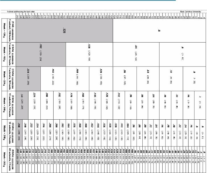
Appendix
All contents are Copyright © 1992–2007 Cisco Systems, Inc. All rights reserved. This document is Cisco Public Information. |
Page 7 of 8 |
CCNA Exploration |
|
Network Fundamentals: |
|
Configuring and Testing Your Network |
Lab 11.5.3 Configure Host Computers for IP Networking |
All contents are Copyright © 1992–2007 Cisco Systems, Inc. All rights reserved. This document is Cisco Public Information. |
Page 8 of 8 |