

7.6.1: Skills Integration Challenge-Data Link Layer Issues
Topology Diagram
Addressing Table
|
Device |
|
Interface |
IP Address |
Subnet Mask |
Default |
|
|
Gateway |
||||
|
|
|
|
|
|
|
|
|
|
|
|
|
|
|
R1-ISP |
Fa0/0 |
|
|
N/A |
|
|
|
|
|
|
||
|
S0/0/0 |
|
|
N/A |
||
|
|
|
|
|
||
|
|
|
|
|
|
|
|
R2- |
Fa0/0 |
|
|
|
|
|
|
|
|
|
||
|
Central |
S0/0/0 |
|
|
|
|
|
|
|
|
|
|
|
|
|
|
|
|
|
|
|
PC 1A |
NIC |
|
|
|
|
|
|
|
|
|
|
|
|
|
|
|
|
|
|
|
PC 1B |
NIC |
|
|
|
|
|
|
|
|
|
|
|
|
|
|
|
|
|
|
|
Eagle |
|
|
|
|
|
|
Server |
NIC |
|
|
|
|
|
|
|
|
|
|
|
All contents are Copyright © 1992–2007 Cisco Systems, Inc. All rights reserved. This document is Cisco Public Information. |
Page 1 of 3 |

CCNA Exploration |
|
Network Fundamentals: |
|
Data Link Layer |
7.6.1: Skills Integration Challenge-Data Link Layer Issues |
Learning Objectives
•IP subnet planning
oPractice your subnetting skills.
•Build the network.
oConnect devices with Ethernet and serial cables.
•Configure the network.
oApply your subnetting scheme to server, PCs, and router interfaces; configure services and static routing.
•Test the network
oUsing ping, trace, web traffic, Inspect tool.
Background
Network Interface Cards (NICs) are sometimes thought of as Layer 2 and Layer 1 devices (or as Layer 2 and Layer 1 components of devices that function at all 7 layers). Sometimes the network interface card for a serial connection, typically used in WAN connections, is called a WAN interface card or WIC. In this challenge you must add a WIC to a device to complete the network. In addition, you have been asked to implement a new IP addressing scheme to the Exploration lab topology.
Task 1: IP Subnet Planning.
You have been given an IP address block of 172.16.0.0 /22. You must provide for existing networks as well as future growth.
Subnet assignments are:
•1st subnet, existing student LAN, up to 400 hosts; (Fa0/0 on R2-Central)
•2nd subnet, future student LAN, up to 180 hosts; (not yet implemented)
•3rd subnet, existing ISP LAN, up to 40 hosts; (Fa0/0 on R1-ISP)
•4th subnet, future ISP LAN, up to 18 hosts; (not yet implemented)
•5th subnet, existing WAN, point-to-point link; (S0/0/0 on R1-ISP and R2-Central)
•6th subnet, future WAN, point-to-point link; (not yet implemented)
•7th subnet, future WAN, point-to-point link. (not yet implemented)
Interface IP addresses:
•For the server, configure the second highest usable IP address on the ISP LAN subnet.
•For R1-ISP's Fa0/0 interface, configure the highest usable IP address on the ISP LAN subnet.
•For R1-ISP's S0/0/0 interface, configure the highest usable address on the existing WAN subnet.
•For R2-Central's S0/0/0 interface, use the lowest usable address on the existing WAN subnet.
•For R2-Central's Fa0/0 interface, use the highest usable address on the existing student LAN subnet.
•For PCs 1A and 1B, use the first 2 IP addresses (two lowest usable addresses) on the existing student LAN subnet.
Additional configurations:
All contents are Copyright © 1992–2007 Cisco Systems, Inc. All rights reserved. This document is Cisco Public Information. |
Page 2 of 3 |

CCNA Exploration |
|
Network Fundamentals: |
|
Data Link Layer |
7.6.1: Skills Integration Challenge-Data Link Layer Issues |
•For PCs 1A and 1B, in addition to IP configuration, configure them to use DNS services.
•For the server, enable DNS services, use the domain name eagle-server.example.com, and enable HTTP services.
Task 2: Finish Building the Network in Packet Tracer, Attending to Some Layer 2 Issues.
On the R2-Central router, a network interface card is missing for the serial connection to R1-ISP: add a WIC-2T in the right hand slot. Also, on R2-Central, the Fa0/0 is shutdown; turn it on. Connect a serial DCE cable to R1-ISP S0/0/0, with the other end to R2-Central S0/0/0. For all devices, make sure the power is on to all device and interfaces.
Task 3: Configure the Network.
You will need to configure the server, both routers, and the two PCs. You will not need to configure the switch nor do you need the IOS CLI to configure the routers. Part of the router configuration has already been done for you: all you must do is configure the static routes and the interfaces via the GUI. The static route on R1-ISP should point to the existing student LAN subnet via R2-Central's serial interface IP address; the static route on R2-Central should be a default static route which points via R1-ISP's serial interface IP address. These procedures were explained in the Chapter 5 Skills Integration Challenge and practiced in the Chapter 6 Skills Integration Challenge.
Task 4: Test the Network.
Use ping, trace, web traffic, and the Inspect tool. Trace packet flow in simulation mode, with HTTP, DNS, TCP, UDP, and ICMP viewable, to test your understanding of how the network is operating. Note in particular what Layer 2 encapsulation is used in each step of a packet's journey, and how the headers on the Layer 2 PDUs change.
Reflection
Consider an ICMP echo request packet sent from PC 1A to Eagle Server and the ICMP echo reply packet that results. What addresses stay the same in this situation, and what addresses change?
All contents are Copyright © 1992–2007 Cisco Systems, Inc. All rights reserved. This document is Cisco Public Information. |
Page 3 of 3 |
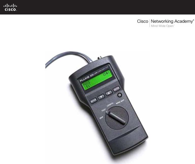
Lab 8.4.1: Media Connectors Lab Activity
Fluke 620 LAN CableMeter
Learning Objectives
Upon completion of this lab, you will be able to:
•Test cables using a Fluke620 LAN CableMeter and a Fluke LinkRunner
•Become familiar with the most common functions of a cable tester.
•Test different cables for type and wiring problems.
Background
Category (CAT 5) unshielded twisted-pair (UTP) cables are wired according to function. End devices, such as routers and host computers, connect to switches with CAT 5 straight-through cables. When connected together, however, a CAT 5 crossover cable must be used. This is also true of switches. When connecting one switch to another, a CAT 5 crossover cable is used again.
All contents are Copyright © 1992–2007 Cisco Systems, Inc. All rights reserved. This document is Cisco Public Information. |
Page 1 of 7 |
CCNA Exploration |
|
Network Fundamentals: OSI Physical Layer |
Lab 8.4.1: Media Connectors Lab Activity |
Problems related to cables are one of the most common causes of network failure. Basic cable tests can be very helpful in troubleshooting cabling problems with UTP. The quality of cabling components used, the routing and installation of the cable, and quality of the connector terminations will be the main factors in determining how trouble-free the cabling will be.
The following resources are required:
•Good CAT 5 straight-through and crossover wired cables of different colors.
•Category 5 straight-through and crossover wired cables with open wire connections in the middle or one or more conductors shorted at one end that are different colors and different lengths.
•Fluke 620 LAN CableMeter or equivalent.
•Fluke LinkRunner
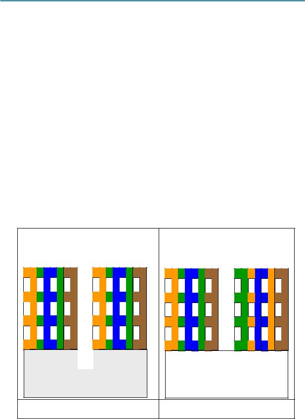
TIA/EIA 568B is different from TIA/EIA 568A wiring. TIA/EIA 568A straight-through cables can be identified by the color coding. Similar to Figure 2, below, the right wiring diagram, starting with the greenwhite cable, will be identical on both ends.
Scenario
First, you will visually determine whether the CAT 5 cable type is crossover or straight-through. Next, you will use the cable tester to verify the cable type, as well as common features available with the tester.
Finally, you will use the cable tester to test for bad cables that cannot be determined with a visual inspection.
Task 1: Become Familiar with the Most Common Functions of a Cable Tester.
TIA/EIA 568B CAT 5 UTP
Straight Through
1 |
2 |
3 |
4 |
5 |
6 |
7 |
8 |
1 |
2 |
3 |
4 |
5 |
6 |
7 |
8 |
TIA/EIA 568B CAT 5 UTP
Crossover
1 |
2 |
3 |
4 |
5 |
6 |
7 |
8 |
1 |
2 |
3 |
4 |
5 |
6 |
7 |
8 |
|
|
|
|
|
|
|
|
Figure 1. Straight-through Wire Location |
Figure 2. Crossover Wire Location |
||
All contents are Copyright © 1992–2007 Cisco Systems, Inc. All rights reserved. This document is Cisco Public Information. |
Page 2 of 7 |

CCNA Exploration |
|
Network Fundamentals: OSI Physical Layer |
Lab 8.4.1: Media Connectors Lab Activity |
Figures 1 and 2 show the TIA/EIA 568B CAT 5 UTP wire positioning for a straight-through and crossover cable, respectively. When CAT 5 connectors are held together, wire color is a quick way to determine the cable type.
Step 1: Visually determine cable types.
There should be two numbered cables available. Perform a visual inspection of the cables and then fill out the chart below with the cable color, cable type, and use:
Cable |
Cable |
Cable Type |
Cable Use |
No. |
Color |
(straight-through or |
(Circle correct device) |
|
|
crossover) |
|
1 |
|
|
Switch to: host / switch |
|
|
|
|
2 |
|
|
Switch to: host / switch |
|
|
|
|
It is now time to verify the cable type and learn about the common features of the cable tester.
Step 2: Perform initial configuration of the Fluke 620 LAN CableMeter.
Turn the rotary switch selector on the tester to the WIRE MAP position. The wire map function displays which pins on one end of the cable are connected to which pins on the other end.
Press the SETUP button to enter the setup mode, and observe the LCD screen on the tester. The first option should be CABLE. Press the UP or DOWN arrow buttons until the desired cable type of UTP is selected. Press ENTER to accept that setting and go to the next one. Continue pressing the UP/DOWN arrows and pressing ENTER until the tester is set to the following cabling settings:
Tester Option |
Desired Setting – UTP |
|
|
CABLE: |
UTP |
WIRING: |
10BASE-T or EIA/TIA 4PR |
|
|
CATEGORY: |
CATEGORY 5 |
WIRE SIZE |
AWG 24 |
|
|
CAL to CABLE? |
NO |
|
|
BEEPING: |
ON or OFF |
|
|
LCD CONTRAST |
From 1 through 10 (brightest) |
When satisfied with the correct settings, press the SETUP button to exit setup mode.
Step 3: Verify cable wire map.
Figure 3. Cable Coupler and Cable Identifier
All contents are Copyright © 1992–2007 Cisco Systems, Inc. All rights reserved. This document is Cisco Public Information. |
Page 3 of 7 |

CCNA Exploration |
|
Network Fundamentals: OSI Physical Layer |
Lab 8.4.1: Media Connectors Lab Activity |
Use the following procedure to test each cable with the LAN cable coupler and cable identifier, shown in Figure 3. The coupler and the cable identifier are accessories that come with the Fluke 620 LAN CableMeter.
Place the near end of the cable into the RJ-45 jack labeled UTP/FTP on the tester. Place the RJ-45-RJ- 45 female coupler on the far end of the cable, and then insert the cable identifier into the other side of the coupler.
The wiring of both the near and far end of the cable will be displayed. The top set of numbers displayed on the LCD screen refers to the near end, and the bottom set of numbers refers to the far end.
Perform a Wire Map test on each of the cables provided, and fill in the following table based on the results. For each cable, write down the number and color, and whether the cable is straight-through or crossover.
Cable |
Cable |
Cable |
No. |
Color |
Type (straight-through or crossover) |
1 |
|
|
|
|
|
2 |
|
|
|
|
|
Note any problems encountered during this test:
Step 4: Verify cable length.
Move the rotary switch selector on the tester to the LENGTH position. If power was cycled, repeat the setup steps described in Step 2. The tester LENGTH function displays the length of the cable.
Perform a basic cable test on each of the cables, and complete the following table based on the results. For each cable, write down the number and color, the cable length, the tester screen test results, and what the problem is, if there is a problem.
Cable |
Cable |
Cable |
No. |
Color |
Length |
1 |
|
|
|
|
|
2 |
|
|
|
|
|
Note any problems encountered during this test:
Repeat these steps until you are comfortable with the use of the cable tester. In the next task, unknown cables will be tested.
Task 2: Test Different Cables for Type and Wiring Problems.
Obtain at least 5 different cables from your instructor. Move the rotary switch selector on the tester to the WIRE MAP position. If power was cycled, repeat the setup steps described in Task 1, Step 2.
Using the cable tester WIRE MAP function, perform a Wire Map test on each of the cables provided. Then fill in the following table based on the result for each Category 5 cable tested. For each cable, write down the number and color, whether the cable is straight-through or crossover, the tester screen test results, and any problem.
All contents are Copyright © 1992–2007 Cisco Systems, Inc. All rights reserved. This document is Cisco Public Information. |
Page 4 of 7 |
CCNA Exploration |
|
Network Fundamentals: OSI Physical Layer |
Lab 8.4.1: Media Connectors Lab Activity |
Cable |
Cable Type |
Cable Color |
Cable type |
* Test Results |
Problem Description |
No. |
(Visual inspection) |
|
(straight- |
|
|
|
|
|
through or |
|
|
|
|
|
crossover) |
|
|
|
|
|
|
|
|
1 |
|
|
|
|
|
|
|
|
|
|
|
2 |
|
|
|
|
|
|
|
|
|
|
|
3 |
|
|
|
|
|
|
|
|
|
|
|
4 |
|
|
|
|
|
|
|
|
|
|
|
5 |
|
|
|
|
|
|
|
|
|
|
|
* Refer to the Fluke manual for detailed description of test results for wire map. |
|||||
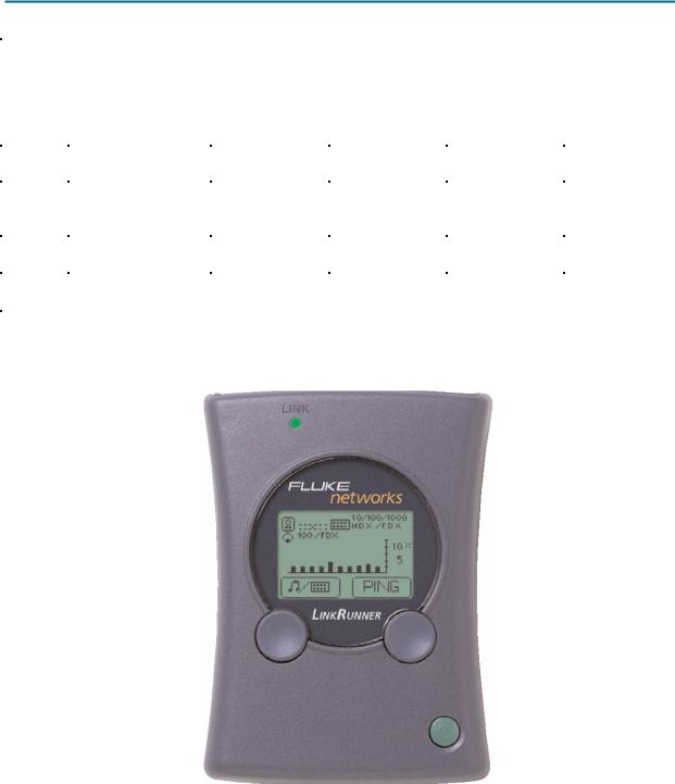
Task 3: Perform initial configuration of the Fluke LinkRunner
Fluke LinkRunner
Step 1: Turn the Fluke LinkRunner on by pressing the green button on the lower right along with the blue button on the right.
Step 2: Press the green button on the lower right to turn it back off.
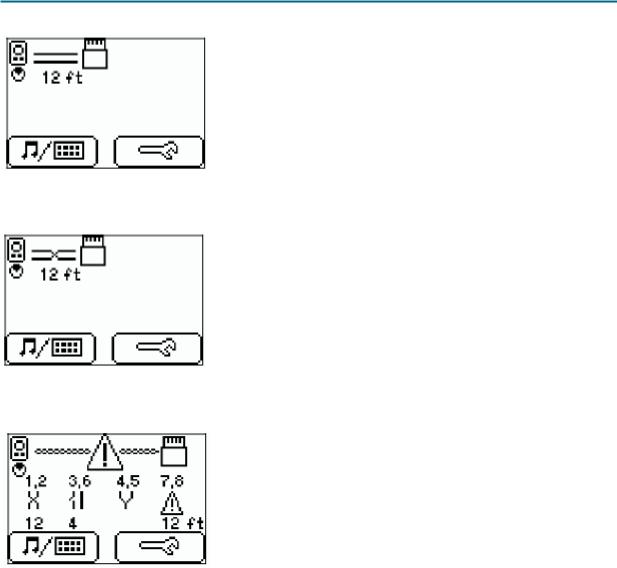
Step 3: Place both ends of the cable into the LAN and MAP ports located on top of the LinkRunner and press the green botton on the lower right along with the blue button to the left.
If it is a correct straight-through cable then two parallel lines (as shown below) will appear on the upper left corner on the screen.
All contents are Copyright © 1992–2007 Cisco Systems, Inc. All rights reserved. This document is Cisco Public Information. |
Page 5 of 7 |
CCNA Exploration |
|
Network Fundamentals: OSI Physical Layer |
Lab 8.4.1: Media Connectors Lab Activity |
If it is a correct crossover cable then two intersecting lines (as shown below) will appear on the upper left corner on the screen.
If it is a bad cable,  will appear and details will be displayed below.
 Open
Open
 Short
Short
 Split
Split
 Reversal
 Unknown
Task 4: Verify Cable Length
Note: The instructions to test a cable are the same as determining cable length.
Step 1: Turn the Fluke LinkRunner on by pressing the green button on the lower right along with the blue button on the right.
Step 2: Press the green button on the lower right to turn it back off.
Step 3: Place both ends of the cable into the LAN and MAP ports located on top of the LinkRunner and press the green botton on the lower right along with the blue button to the left.
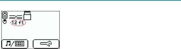
Step 4: Locate the length of the cable below the icon indicating the type of cable (as shown below).
All contents are Copyright © 1992–2007 Cisco Systems, Inc. All rights reserved. This document is Cisco Public Information. |
Page 6 of 7 |
CCNA Exploration |
|
Network Fundamentals: OSI Physical Layer |
Lab 8.4.1: Media Connectors Lab Activity |
Task 5: Reflection
Problems related to cables are one of the most common causes of network failure. Network technicians should be able to determine when to use CAT 5 UTP straight-through and crossover cables.
A cable tester is used to determine cable type, length, and wire map. In a lab environment, cables are constantly moved and reconnected. A properly functioning cable today may be broken tomorrow. This isn’t unusual, and is part of the learning process.
Task 6: Challenge
Look for opportunities to test other cables with the Fluke 620 LAN CableMeter. Skills learned in this lab will enable you to quickly troubleshoot wrong cable types and broken cables.
Task 7: Clean Up
The cable tester is very expensive and should never be left unattended. Return the cable tester to the instructor when finished.
Ask the instructor where to return used cables. Store the cables neatly for the next class.
All contents are Copyright © 1992–2007 Cisco Systems, Inc. All rights reserved. This document is Cisco Public Information. |
Page 7 of 7 |
8.5.1: Skills Integration Challenge-Connecting Devices and
Exploring the Physical View
Topology Diagram:
Addressing Table
|
Device |
|
Interface |
IP Address |
Subnet Mask |
Default |
|
|
Gateway |
||||
|
|
|
|
|
|
|
|
|
|
|
|
|
|
|
R1-ISP |
Fa0/0 |
192.168.254.253 |
255.255.255.0 |
N/A |
|
|
|
|
|
|
||
|
S0/0/0 |
10.10.10.6 |
255.255.255.252 |
N/A |
||
|
|
|
||||
|
|
|
|
|
|
|
|
R2- |
Fa0/0 |
172.16.255.254 |
255.255.0.0 |
10.10.10.6 |
|
|
|
|
|
|
||
|
Central |
S0/0/0 |
10.10.10.5 |
255.255.255.252 |
10.10.10.6 |
|
|
|
|
||||
|
|
|
|
|
|
|
|
S1- |
VLAN 1 |
172.16.254.1 |
255.255.0.0 |
172.16.255.254 |
|
|
Central |
|||||
|
|
|
|
|
||
|
PC 1A |
NIC |
172.16.1.1 |
255.255.0.0 |
172.16.255.254 |
|
|
|
|
||||
|
|
|
|
|
|
|
|
PC 1B |
NIC |
172.16.1.2 |
255.255.0.0 |
172.16.255.254 |
|
|
|
|
||||
|
|
|
|
|
|
|
|
Eagle |
|
|
|
|
|
|
Server |
NIC |
192.168.254.254 |
255.255.255.0 |
192.168.254.253 |
|
|
|
|
|
|
|
|
All contents are Copyright © 1992–2007 Cisco Systems, Inc. All rights reserved. This document is Cisco Public Information. |
Page 1 of 3 |

CCNA Exploration |
|
Network Fundamentals: |
|
OSI Physical Layer |
8.5.1: Skills Integration Challenge-Connecting Devices and Exploring the Physical View |
Learning Objectives
•Connect the devices in the standard lab setup o Connect the devices
o Verify connectivity
•View the standard lab setup in the Physical Workspace o Enter and view the Physical Workspace
o View the standard lab setup at the various levels of the Physical Workspace
Introduction
When working in Packet Tracer, in a lab environment, or in a corporate setting it is important to know how to select the proper cable and how to properly connect devices. This activity will examine device configurations in Packet Tracer, select the proper cable based on the configuration, and connect the devices. This activity will also explore the physical view of the network in Packet Tracer.
Task 1: Connect the Devices in the Standard Lab Setup.
Step 1: Connect the devices.
Connect PC 1A to the first port on switch S1-Central and PC 1B to the second port on switch S1Central using the proper cable.
Click on router R2-Central and examine the configuration using the Config tab. Connect the proper interface on the router to Interface FastEthernet0/24 on switch S1-Central using the proper cable.
Click on both routers and examine the configuration using the Config tab. Connect the routers together using the proper interfaces and the proper cable
Click on router R1-ISP and examine the configuration using the Config tab. Connect the proper interface on the router to the proper interface on Eagle Server using the proper cable.
Step 2: Verify connectivity.
From the Command Prompt on the Desktop of both PCs issue the command ping 192.168.254.254, the IP address of Eagle Server. If the pings fail, check your connections and troubleshoot until the pings succeeds. Check your configuration by clicking the Check Results button.
Task 2: View the Standard Lab Setup in the Physical Workspace.
Step 1: Enter and view the Physical Workspace.
Most of our work in Packet Tracer has been done in the Logical Workspace. In an internetwork, routers maybe in different sites from across the street to across the globe. The serial link between the routers represents a dedicated leased line between two locations consisting of a DTE (Data Terminal Equipment), such as a router, connected to a DCE (Data Communication Equipment), such as a CSU/DSU or modem. The DCE connects to a service provider's local loop and the connections are repeated at the other end of the link. The Physical Workspace allows us to see these relationships more clearly.
All contents are Copyright © 1992–2007 Cisco Systems, Inc. All rights reserved. This document is Cisco Public Information. |
Page 2 of 3 |

CCNA Exploration |
|
Network Fundamentals: |
|
OSI Physical Layer |
8.5.1: Skills Integration Challenge-Connecting Devices and Exploring the Physical View |
Enter the Physical Workspace by clicking the tab in the upper left hand corner of the Workspace. It shows the connection between Central City and ISP City.
Step 2: View the standard lab setup at the various levels of the Physical Workspace.
Click on the Central City, it shows the city and the location of the Central Office building. Click on the Central Office building, it shows the floor plan of the building and the loaction of the Wiring Closet. Click on the Wiring Closet, it shows a physical representation of the equipment installed in the wiring closet and the cabling that connects the equipment. Examine this view of the topology.
Click on Intercity on the Navigation bar. Repeat the steps to view the equipment installed in ISP City.
All contents are Copyright © 1992–2007 Cisco Systems, Inc. All rights reserved. This document is Cisco Public Information. |
Page 3 of 3 |