

Lab 6.7.5: Subnet and Router Configuration
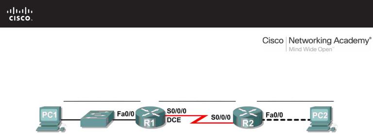
Topology Diagram
Addressing Table
|
Device |
|
|
Interface |
|
|
IP Address |
|
|
Subnet Mask |
|
|
Default Gateway |
|
|
|
|
|
|
|
|
|
|
|
|||||
|
|
|
|
|
|
|
|
|
|
|
|
|
|
|
|
R1 |
|
Fa0/0 |
|
|
|
|
|
|
|
N/A |
|||
|
|
|
|
|
|
|
|
|
|
|
|
|
||
|
|
S0/0/0 |
|
|
|
|
|
|
|
N/A |
||||
|
|
|
|
|
|
|
|
|
|
|
||||
|
|
|
|
|
|
|
|
|
|
|
|
|
||
|
R2 |
|
Fa0/0 |
|
|
|
|
|
|
|
N/A |
|||
|
|
|
|
|
|
|
|
|
|
|
|
|
||
|
|
S0/0/0 |
|
|
|
|
|
|
|
N/A |
||||
|
|
|
|
|
|
|
|
|
|
|
||||
|
|
|
|
|
|
|
|
|
|
|
|
|
||
|
PC1 |
|
NIC |
|
|
|
|
|
|
|
|
|
||
|
|
|
|
|
|
|
|
|
|
|
|
|
||
|
PC2 |
|
NIC |
|
|
|
|
|
|
|
|
|
||
|
|
|
|
|
|
|
|
|
|
|
|
|
|
|
Learning Objectives
Upon completion of this lab, you will be able to:
•Subnet an address space given requirements.
•Assign appropriate addresses to interfaces and document.
•Configure and activate Serial and FastEthernet interfaces.
•Test and verify configurations.
•Reflect upon and document the network implementation.
Scenario
In this lab activity, you will design and apply an IP addressing scheme for the topology shown in the Topology Diagram. You will be given one address block that you must subnet to provide a logical addressing scheme for the network. The routers will then be ready for interface address configuration according to your IP addressing scheme. When the configuration is complete, verify that the network is working properly.
All contents are Copyright © 1992–2007 Cisco Systems, Inc. All rights reserved. This document is Cisco Public Information. |
Page 1 of 3 |

CCNA Exploration |
|
Network Fundamentals: Addressing the Network - IPV4 |
Lab 6.7.1: Subnet and Router Configuration |
Task 1: Subnet the Address Space.
Step 1: Examine the network requirements.
You have been given the 192.168.1.0/24 address space to use in your network design. The network consists of the following segments:
•The network connected to router R1 will require enough IP addresses to support 15 hosts.
•The network connected to router R2 will require enough IP addresses to support 30 hosts.
•The link between router R1 and router R2 will require IP addresses at each end of the link.
Step 2: Consider the following questions when creating your network design.
How many subnets are needed for this network? ____________________
What is the subnet mask for this network in dotted decimal format? ____________________
What is the subnet mask for the network in slash format? ____________________
How many usable hosts are there per subnet? ____________________
Step 3: Assign subnetwork addresses to the Topology Diagram.
1.Assign subnet 1 to the network attached to R1.
2.Assign subnet 2 to the link between R1 and R2.
3.Assign subnet 3 to the network attached to R2.
Task 2: Determine Interface Addresses.
Step 1: Assign appropriate addresses to the device interfaces.
1.Assign the first valid host address in subnet 1 to the LAN interface on R1.
2.Assign the last valid host address in subnet 1 to PC1.
3.Assign the first valid host address in subnet 2 to the WAN interface on R1.
4.Assign the last valid host address in subnet 2 to the WAN interface on R2.
5.Assign the first valid host address in subnet 3 to the LAN interface of R2.
6.Assign the last valid host address in subnet 3 to PC2.
Step 2: Document the addresses to be used in the table provide under the Topology Diagram.
Task 3: Configure the Serial and FastEthernet Addresses.
Step 1: Configure the router interfaces.
Configure the interfaces on the R1 and R2 routers with the IP addresses from your network design. Please note, to complete the activity in Packet Tracer you will be using the Config Tab. When you have finished, be sure to save the running configuration to the NVRAM of the router.
Step 2: Configure the PC interfaces.
Configure the Ethernet interfaces of PC1 and PC2 with the IP addresses and default gateways from your network design.
All contents are Copyright © 1992–2007 Cisco Systems, Inc. All rights reserved. This document is Cisco Public Information. |
Page 2 of 3 |

CCNA Exploration |
|
Network Fundamentals: Addressing the Network - IPV4 |
Lab 6.7.1: Subnet and Router Configuration |
Task 4: Verify the Configurations.
Answer the following questions to verify that the network is operating as expected. From the host attached to R1, is it possible to ping the default gateway? __________
From the host attached to R2, is it possible to ping the default gateway? __________
From the router R1, is it possible to ping the Serial 0/0/0 interface of R2? __________
From the router R2, is it possible to ping the Serial 0/0/0 interface of R1? __________
Task 5: Reflection
Are there any devices on the network that cannot ping each other?
__________________________________________________________________________
__________________________________________________________________________
What is missing from the network that is preventing communication between these devices?
__________________________________________________________________________
__________________________________________________________________________
All contents are Copyright © 1992–2007 Cisco Systems, Inc. All rights reserved. This document is Cisco Public Information. |
Page 3 of 3 |
6.8.1: Skills Integration Challenge-Planning Subnets and
Configuring IP Addresses
Topology Diagram
Addressing Table
|
Device |
|
Interface |
IP Address |
Subnet Mask |
Default |
|
|
Gateway |
||||
|
|
|
|
|
|
|
|
|
|
|
|
|
|
|
R1-ISP |
Fa0/0 |
|
|
N/A |
|
|
|
|
|
|
||
|
S0/0/0 |
|
|
N/A |
||
|
|
|
|
|
||
|
|
|
|
|
|
|
|
R2- |
Fa0/0 |
|
|
|
|
|
|
|
|
|
||
|
Central |
S0/0/0 |
|
|
|
|
|
|
|
|
|
|
|
|
|
|
|
|
|
|
|
PC 1A |
NIC |
|
|
|
|
|
|
|
|
|
|
|
|
|
|
|
|
|
|
|
PC 1B |
NIC |
|
|
|
|
|
|
|
|
|
|
|
|
|
|
|
|
|
|
|
Eagle |
|
|
|
|
|
|
Server |
NIC |
|
|
|
|
|
|
|
|
|
|
|
All contents are Copyright © 1992–2007 Cisco Systems, Inc. All rights reserved. This document is Cisco Public Information. |
Page 1 of 3 |

CCNA Exploration |
|
Network Fundamentals: |
|
Addressing the Network - IPv4 |
6.8.1: Skills Integration Challenge-Planning Subnets and Configuring IP Addresses |
Learning Objectives
•IP Subnet Planning
oPractice your subnetting skills.
•Build the Network.
oConnect devices with Ethernet and serial cables.
•Configure the network.
oApply your subnetting scheme to server, PCs, and router interfaces; configure services and static routing.
•Test the network.
oUsing ping, trace, web traffic, Inspect tool
Background
You have been asked to implement the standard lab topology, but with a new IP addressing scheme. You will use many of the skills you have learned to this point in the course.
Task 1: IP Subnet Planning
You have been given an IP address block of 192.168.23.0 /24. You must provide for existing networks as well as future growth.
Subnet assignments are:
•1st subnet, existing student LAN (off of router R2-Central), up to 60 hosts;
•2nd subnet, future student LAN, up to 28 hosts;
•3rd subnet, existing ISP LAN, up to 12 hosts;
•4th subnet, future ISP LAN, up to 8 hosts;
•5th subnet, existing WAN, point-to-point link;
•6th subnet, future WAN, point-to-point link;
•7th subnet, future WAN, point-to-point link. Interface IP addresses:
•For the server, configure the second highest usable IP address on the existing ISP LAN subnet.
•For R1-ISP's Fa0/0 interface, configure the highest usable IP address on the existing ISP LAN subnet.
•For R1-ISP's S0/0/0 interface, configure the highest usable address on the existing WAN subnet.
•For R2-Central's S0/0/0 interface, use the lowest usable address on the existing WAN subnet.
•For R2-Central's Fa0/0 interface, use the highest usable address on the existing student LAN subnet.
•For hosts 1A and 1B, use the first 2 IP addresses (two lowest usable addresses) on the existing student LAN subnet.
All contents are Copyright © 1992–2007 Cisco Systems, Inc. All rights reserved. This document is Cisco Public Information. |
Page 2 of 3 |

CCNA Exploration |
|
Network Fundamentals: |
|
Addressing the Network - IPv4 |
6.8.1: Skills Integration Challenge-Planning Subnets and Configuring IP Addresses |
Additional configurations:
•For PCs 1A and 1B, in addition to IP configuration, configure them to use DNS services.
•For the server, enable DNS services, use the domain name eagle-server.example.com, and enable HTTP services.
•For R1-ISP router serial interface, you will need to set the clock rate (a timing mechanism required on the DCE end of serial links) to 64000.
•No clock rate is needed on the DTE side, in this case R2-Central's serial interface.
Task 2: Finish Building the Network in Packet Tracer.
Add cables where missing.
•Connect a serial DCE cable to R1-ISP S0/0/0, with the other end to R2-Central S0/0/0.
•Connect PC 1A to the first FastEthernet port on switch S1-Central.
•Connect PC 1B to the second FastEthernet port on switch S1-Central.
•Connect interface Fa0/0 on router R2-Central to the highest FastEthernet port on switch S1-Central.
•For all devices, make sure the power is on to the device and the interfaces.
Task 3: Configure the Network.
You will need to configure the server, both routers, and the two PCs. You will not need to configure the switch nor do you need the IOS CLI to configure the routers. Part of the router configuration has already been done for you: all you must do is configure the static routes and the interfaces via the GUI. The static route on R1-ISP should point to the existing student LAN subnet via R2-Central's serial interface IP address; the static route on R2-Central should be a default static route which points via R1-ISP's serial interface IP address. These procedures were explained in the Chapter 5 Skills Integration Challenge.
Task 4: Test the Network.
Use ping, trace, web traffic, and the Inspect tool. Trace packet flow in simulation mode, with HTTP, DNS, TCP, UDP, and ICMP viewable, to test your understanding of how the network is operating.
Reflection
Reflect upon how much you have learned so far! Practicing IP subnetting skills and networking building, configuration and testing skills will serve you well throughout your networking courses.
All contents are Copyright © 1992–2007 Cisco Systems, Inc. All rights reserved. This document is Cisco Public Information. |
Page 3 of 3 |