
- •Activity 1.1.1: Using Google Earth™ to View the World
- •Activity 1.4.5: Identifying Top Security Vulnerabilities
- •Lab 1.6.1: Using Collaboration Tools— IRC and IM
- •Lab 1.6.2: Using Collaboration Tools—Wikis and Web Logs
- •1.7.1: Skills Integration Challenge-Introduction to Packet Tracer
- •Activity 2.2.5: Using NeoTrace™ to View Internetworks
- •Lab 2.6.1: Topology Orientation and Building a Small Network
- •Lab 2.6.2: Using Wireshark™ to View Protocol Data Units
- •2.7.1: Skills Integration Challenge-Examining Packets
- •Activity 3.4.1: Data Stream Capture
- •Lab 3.4.2: Managing a Web Server
- •Lab 3.4.3: E-mail Services and Protocols
- •Lab 4.5.1: Observing TCP and UDP using Netstat
- •Lab 4.5.2: TCP/IP Transport Layer Protocols, TCP and UDP
- •Lab 4.5.3: Application and Transport Layer Protocols Examination
- •Lab 5.5.1: Examining a Device’s Gateway
- •Lab 5.5.2: Examining a Route
- •5.6.1: Skills Integration Challenge-Routing IP Packets
- •Lab 6.7.1: Ping and Traceroute
- •Lab 6.7.2: Examining ICMP Packets
- •Activity 6.7.3: IPv4 Address Subnetting Part 1
- •Activity 6.7.4: IPv4 Address Subnetting Part 2
- •Lab 6.7.5: Subnet and Router Configuration
- •Lab 7.5.2: Frame Examination
- •7.6.1: Skills Integration Challenge-Data Link Layer Issues
- •Lab 8.4.1: Media Connectors Lab Activity
- •Lab 9.8.1: Address Resolution Protocol (ARP)
- •Lab 9.8.2: Cisco Switch MAC Table Examination
- •Lab 9.8.3: Intermediary Device as an End Device
- •9.9.1: Skills Integration Challenge-Switched Ethernet
- •Lab 10.3.2: How Many Networks?
- •Lab 10.6.1: Creating a Small Lab Topology
- •Lab 10.6.2: Establishing a Console Session with HyperTerminal
- •Lab 10.6.3: Establishing a Console Session with Minicom
- •11.4.3.3: Network Latency Documentation with Ping
- •Lab 11.5.1: Basic Cisco Device Configuration
- •Lab 11.5.2: Managing Device Configuration
- •Lab 11.5.3: Configure Host Computers for IP Networking
- •Lab 11.5.4: Network Testing
- •Lab 11.5.5: Network Documentation with Utility Commands
- •Lab 11.5.6: Final Case Study - Datagram Analysis with Wireshark
Lab 3.4.3: E-mail Services and Protocols
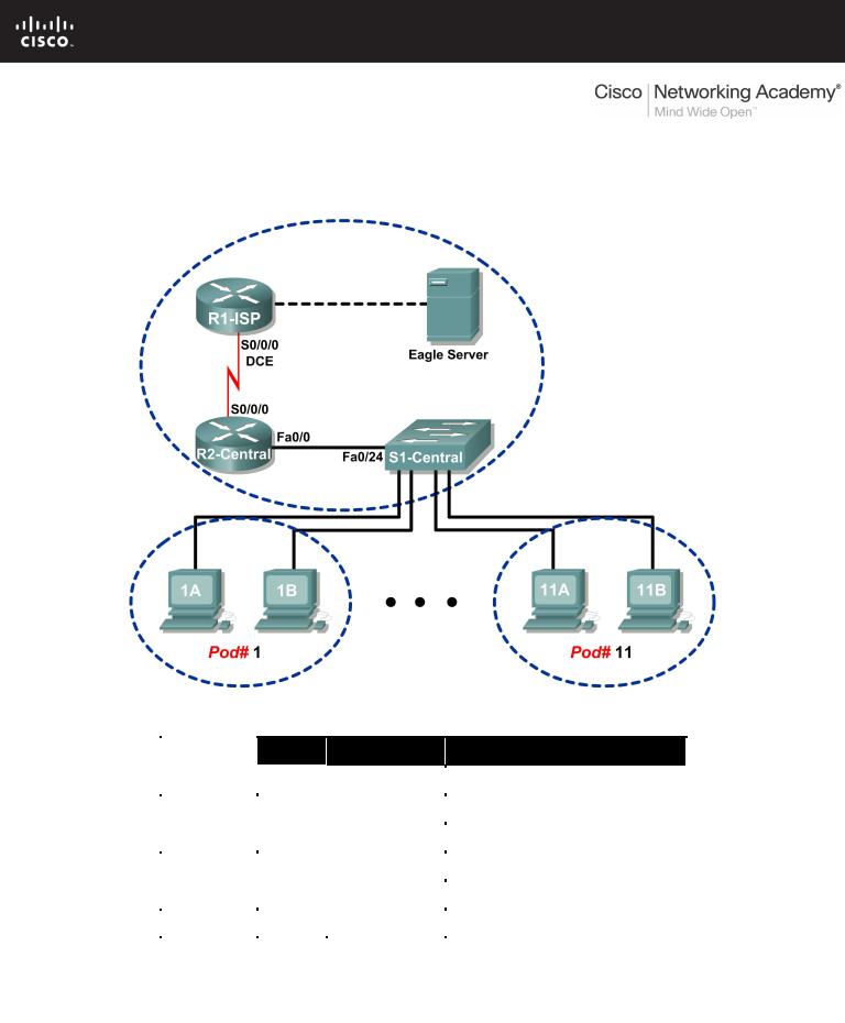
Topology Diagram
Addressing Table
Device |
Interface |
IP Address |
Subnet Mask |
Default Gateway |
|
|
|
|
|
|
|
R1-ISP |
S0/0/0 |
10.10.10.6 |
255.255.255.252 |
N/A |
|
|
|
|
|
||
Fa0/0 |
192.168.254.253 |
255.255.255.0 |
N/A |
||
|
|||||
|
|
|
|
|
|
R2-Central |
S0/0/0 |
10.10.10.5 |
255.255.255.252 |
10.10.10.6 |
|
|
|
|
|
||
Fa0/0 |
172.16.255.254 |
255.255.0.0 |
N/A |
||
|
|||||
|
|
|
|
|
|
|
N/A |
192.168.254.254 |
255.255.255.0 |
192.168.254.253 |
|
Eagle Server |
|
||||
|
|
|
|
||
N/A |
172.31.24.254 |
255.255.255.0 |
N/A |
||
|
|
||||
|
|
|
|
|
|
hostPod#A |
N/A |
172.16. Pod#.1 |
255.255.0.0 |
172.16.255.254 |
|
|
|||||
|
|
|
|
|
|
hostPod#B |
N/A |
172.16. Pod#.2 |
255.255.0.0 |
172.16.255.254 |
|
|
|||||
|
|
|
|
|
|
S1-Central |
N/A |
172.16.254.1 |
255.255.0.0 |
172.16.255.254 |
|
|
|||||
|
|
|
|
|
All contents are Copyright © 1992–2007 Cisco Systems, Inc. All rights reserved. This document is Cisco Public Information. Page 1 of 7

CCNA Exploration |
|
Network Fundamentals: |
|
Application Layer Functionality and Protocols |
Lab 3.4.3: E-mail Services and Protocols |
Learning Objectives
Upon completion of this lab, you will be able to:
•Configure the pod host computer for e-mail service
•Capture and analyze e-mail communication between the pod host computer and a mail server
Background
E-mail is one of the most popular network services that uses a client/server model. The e-mail client is configured on a user’s computer, and configured to connect to an e-mail server. Most Internet service providers (ISPs) provide step-by-step instructions for using e-mail services; consequently, the typical user may be unaware of the complexities of e-mail or the protocols used.
In network environments where the MUA client must connect to an e-mail server on another network to send and receive e-mail, the following two protocols are used:
•Simple Mail Transfer Protocol (SMTP) was originally defined in RFC 821, August, 1982, and has undergone many modifications and enhancements. RFC 2821, April, 2001, consolidates and updates previous e-mail -related RFCs. The SMTP server listens on well-known TCP port 25. SMTP is used to send e-mail messages from the external e-mail client to the e-mail server, deliver e-mail to local accounts, and relay e-mail between SMTP servers.
•Post Office Protocol version 3 (POPv3) — is used when an external e-mail client wishes to receive e-mail messages from the e-mail server. The POPv3 server listens on well-known TCP port 110 .
Earlier versions of both protocols should not be used. Also, there are secure versions of both protocols that employ secure socket layers/Transport layer security (SSL/TSL) for communication.
E-mail is subject to multiple computer security vulnerabilities. Spam attacks flood networks with useless, unsolicited e-mail, consuming bandwidth and network resources. E-mail servers have had numerous vulnerabilities, which left the computer open to compromise.
Scenario
In this lab, you will configure and use an e-mail client application to connect to eagle-server network services. You will monitor the communication with Wireshark and analyze the captured packets.
An e-mail client such as Outlook Express or Mozilla Thunderbird will be used to connect to the eagleserver network service. Eagle-server has SMTP mail services preconfigured, with user accounts capable of sending and receiving external e-mail messages.
Task 1: Configure the Pod Host Computer for E-mail Service.
The lab should be configured as shown in the Topology Diagram and logical address table. If it is not, ask the instructor for assistance before proceeding.
Step 1: Download and install Mozilla Thunderbird.
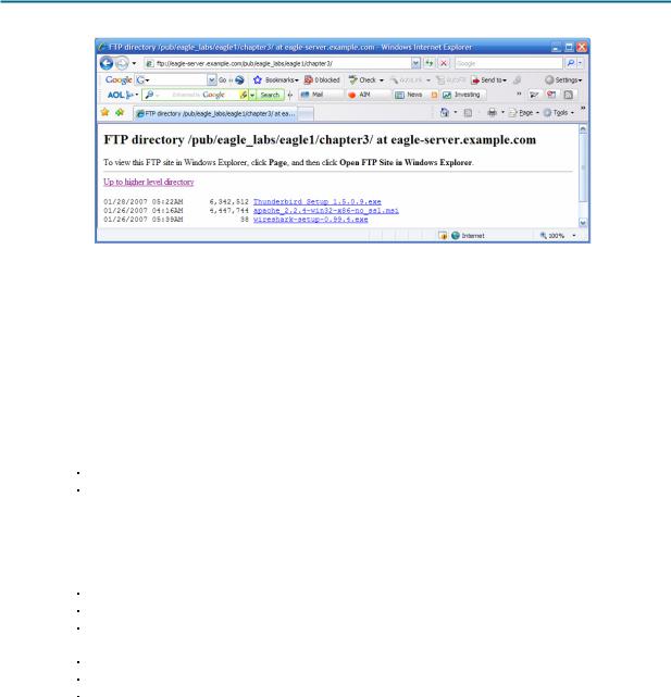
If Thunderbird is not installed on the pod host computer, it can be downloaded from eagleserver.example.com. See Figure 1. The download URL is ftp://eagleserver.example.com/pub/eagle_labs/eagle1/chapter3.
All contents are Copyright © 1992–2007 Cisco Systems, Inc. All rights reserved. This document is Cisco Public Information. |
Page 2 of 7 |
CCNA Exploration |
|
Network Fundamentals: |
|
Application Layer Functionality and Protocols |
Lab 3.4.3: E-mail Services and Protocols |
Figure 1. FTP Download for Wireshark
1.Right-click the Thunderbird filename, and then save the file to the host pod computer.
2.When the file has downloaded, double-click the filename and install Thunderbird with the default settings.
3.When finished, start Thunderbird.
Step 2: Configure Thunderbird to receive and send e-mail messages.
1.When Thunderbird starts, e-mail account settings must be configured. Fill in the Account information as follows:
Field |
Value |
Account Name |
The account name is based on the pod and host |
|
computer. There are a total of 22 accounts |
|
configured on Eagle Server, labeled ccna[1..22]. If |
|
this pod host is on Pod1, Host A, then the account |
|
name is ccna1. If the pod host is on Pod 3, Host B, |
|
then the account name is ccna6. And so on. |
Your Name |
Use the same name as above. |
E-mail address |
Your_name@eagle-server.example.com |
Type of incoming server |
POP |
you are using |
|
Incoming Server (SMTP) |
eagle-server.example.com |
Outgoing Server (SMTP) |
eagle-server.example.com |
All contents are Copyright © 1992–2007 Cisco Systems, Inc. All rights reserved. This document is Cisco Public Information. |
Page 3 of 7 |
CCNA Exploration |
|
Network Fundamentals: |
|
Application Layer Functionality and Protocols |
Lab 3.4.3: E-mail Services and Protocols |
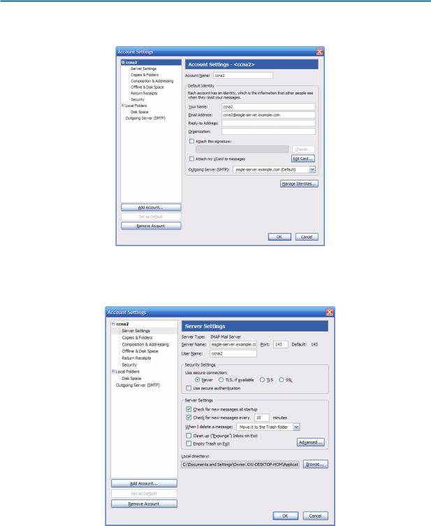
2. Verify account settings from Tools > Account Settings. See Figure 2.
Figure 2. Thunderbird Account Settings
3.In the left pane of the Account Settings screen, click Server Settings. A screen similar to the one shown in Figure 3 will displayed.
Figure 3. Thunderbird Server Settings Screen
All contents are Copyright © 1992–2007 Cisco Systems, Inc. All rights reserved. This document is Cisco Public Information. |
Page 4 of 7 |
CCNA Exploration |
|
Network Fundamentals: |
|
Application Layer Functionality and Protocols |
Lab 3.4.3: E-mail Services and Protocols |
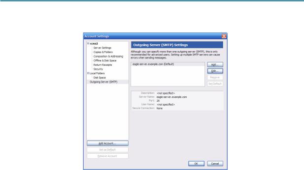
Figure 4 shows the proper configuration for the Outgoing Server (SMTP).
Figure 4. Outgoing Server (SMTP) Settings Screen
What is the purpose of the SMTP protocol, and what is the well-known TCP port number?
____________________________________________________________________________
____________________________________________________________________________
Task 2: Capture and Analyze E-mail Communication between the Pod Host Computer and an E-mail Server.
Step 1: Send an uncaptured e-mail.
1.Ask another student in the class for his or her e-mail name.
2.Using this name, compose and send a friendly message to the student.
Step 2: Start Wireshark captures.
When you are certain that the e-mail operation is working properly for both sending and receiving, start a Wireshark capture. Wireshark will display captures based on packet type.
Step 3: Analyze a Wireshark capture session of SMTP.
1.Using the e-mail client, again send and receive e-mail to a classmate. This time, however, the e- mail transactions will be captured.
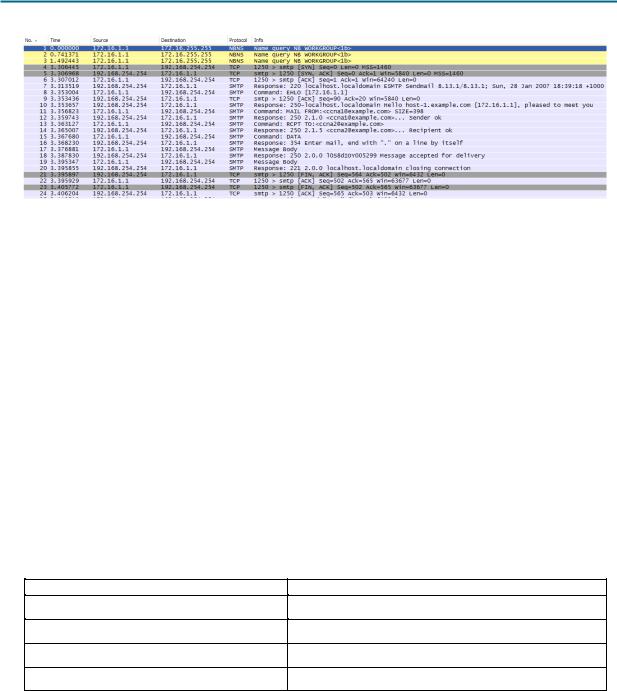
2.After sending and receiving one e-mail message, stop the Wireshark capture. A partial Wireshark capture of an outgoing e-mail message using SMTP is shown in Figure 5.
All contents are Copyright © 1992–2007 Cisco Systems, Inc. All rights reserved. This document is Cisco Public Information. |
Page 5 of 7 |
CCNA Exploration |
|
Network Fundamentals: |
|
Application Layer Functionality and Protocols |
Lab 3.4.3: E-mail Services and Protocols |
Figure 5. SMTP Capture
3.Highlight the first SMTP capture in the top Wireshark window. In Figure 5, this is line number 7.
4.In the second Wireshark window, expand the Simple Mail Transfer Protocol record.
There are many different types of SMTP servers. Malicious attackers can gain valuable knowledge simply by learning the SMTP server type and version.
What is the SMTP server name and version?
____________________________________________________________________________
E-mail client applications send commands to e-mail servers, and e-mail servers send responses. In every first SMTP exchange, the e-mail client sends the command EHLO. The syntax may vary between clients, however, and the command may also be HELO or HELLO. The e-mail server must respond to the command.
What is the SMTP server response to the EHLO command?
____________________________________________________________________________
The next exchanges between the e-mail client and server contain e-mail information. Using your Wireshark capture, fill in the e-mail server responses to the e-mail client commands:
E-mail Client |
E-mail Server |
MAIL FROM:,ccna1@excmaple.com>
RCPT TO:<ccna2@example.com>
DATA
(message body is sent)
What are the contents of the last message body from the e-mail client?
____________________________________________________________________________
How does the e-mail server respond?
____________________________________________________________________________
All contents are Copyright © 1992–2007 Cisco Systems, Inc. All rights reserved. This document is Cisco Public Information. |
Page 6 of 7 |
CCNA Exploration |
|
Network Fundamentals: |
|
Application Layer Functionality and Protocols |
Lab 3.4.3: E-mail Services and Protocols |
Task 3: Challenge
Access a computer that has Internet access. Look up the SMTP server name and version for known weaknesses or compromises. Are there any newer versions available?
Task 4: Reflection
E-mail is probably the most common network service used. Understanding the flow of traffic with the SMTP protocol will help you understand how the protocol manages the client/server data connection. E- mail can also experience configuration issues. Is the problem with the e-mail client or e-mail server? One simple way to test SMTP server operation is to use the Windows command line Telnet utility to telnet into the SMTP server.
1.To test SMTP operation, open the Windows command line window and begin a Telnet session with the SMTP server.
C:\>telnet eagle-server.example.com 25
220 localhost.localdomain ESMTP Sendmail 8.13.1/8.13.1; Sun, 28 Jan
2007 20:41:0
3 +1000
HELO eagle-server.example.com
250 localhost.localdomain Hello [172.16.1.2], pleased to meet you
MAIL From: ccna2@example.com
250 2.1.0 ccna2@example.com... Sender ok
RCPT To: instructor@example.com
250 2.1.5 instructor@example.com... Recipient ok
DATA
354 Please start mail input. e-mail SMTP server test...
.
250 Mail queued for delivery.
QUIT
221 Closing connection. Good bye. Connection to host lost.
C:\ >
Task 5: Clean Up
If Thunderbird was installed on the pod host computer for this lab, the instructor may want the application removed. To remove Thunderbird, click Start > Control Panel > Add or Remove Programs. Scroll to and click Thunderbird, and then click Remove.
Unless directed otherwise by the instructor, turn off power to the host computers. Remove anything that was brought into the lab, and leave the room ready for the next class.
All contents are Copyright © 1992–2007 Cisco Systems, Inc. All rights reserved. This document is Cisco Public Information. |
Page 7 of 7 |
3.5.1: Skills Integration Challenge-Configuring Hosts and
Services
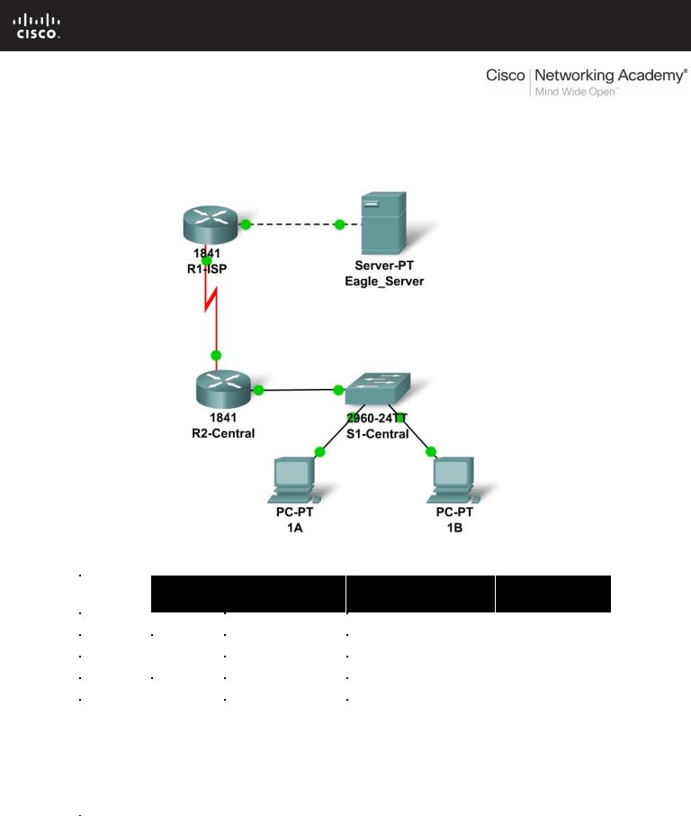
Topology Diagram
Addressing Table
|
Device |
|
Interface |
IP Address |
Subnet Mask |
Default |
|
|
Gateway |
||||
|
|
|
|
|
|
|
|
|
|
|
|
|
|
|
R1-ISP |
Fa0/0 |
192.168.254.253 |
255.255.255.0 |
N/A |
|
|
|
|
|
|
||
|
S0/0/0 |
10.10.10.6 |
255.255.255.252 |
N/A |
||
|
|
|
||||
|
|
|
|
|
|
|
|
R2- |
Fa0/0 |
172.16.255.254 |
255.255.0.0 |
10.10.10.6 |
|
|
|
|
|
|
||
|
Central |
S0/0/0 |
10.10.10.5 |
255.255.255.252 |
10.10.10.6 |
|
|
|
|
||||
|
|
|
|
|
|
|
|
S1- |
VLAN 1 |
172.16.254.1 |
255.255.0.0 |
172.16.255.254 |
|
|
Central |
|||||
|
|
|
|
|
||
|
|
|
|
|
|
|
|
PC 1A |
NIC |
172.16.1.1 |
255.255.0.0 |
172.16.255.254 |
|
|
|
|
||||
|
|
|
|
|
|
|
|
PC 1B |
NIC |
172.16.1.2 |
255.255.0.0 |
172.16.255.254 |
|
|
|
|
||||
|
|
|
|
|
|
|
|
Eagle |
|
|
|
|
|
|
Server |
NIC |
192.168.254.254 |
255.255.255.0 |
192.168.254.253 |
|
|
|
|
|
|
|
|
All contents are Copyright © 1992–2007 Cisco Systems, Inc. All rights reserved. This document is Cisco Public Information. |
Page 1 of 2 |

CCNA Exploration |
|
Network Fundamentals: |
|
Application Layer Functionality and Protocols |
3.5.1: Skills Integration Challenge-Configuring Hosts and Services |
Learning Objectives
•Configure Hosts and Services
•Add, configure, and connect hosts and servers
•Explore How DNS and HTTP Work Together
•Use simulation mode to view the details of packets generated by DNS and HTTP
Background
Throughout the course you will be using a standard lab setup created from actual PCs, servers, routers, and switches to learn networking concepts. At the end of each chapter, you will build increasingly larger parts of this topology in Packet Tracer.
Task 1: "Repair" and Test the Topology.
Add a PC with a display name of 1B to the topology. Configure it with the following settings: IP Address 172.16.1.2, Subnet Mask 255.255.0.0, Default Gateway 172.16.255.254, and DNS Server 192.168.254.254. Connect PC 1B to the Fa0/2 port of the S1-Central switch.
Connect the Eagle Server to the Fa0/0 port on the R1-ISP router. Turn on web services on the server by enabling HTTP. Enable DNS services and add a DNS entry that associates "eagleserver.example.com" (without quotes) with the IP address of the server. Verify your work using feedback from the Check Results button and the Assessment Items tab. Test connectivity, in realtime, by using ADD SIMPLE PDU to test connectivity between PC 1B and the Eagle Server.
Note that when you add a simple PDU, it appears in the PDU List Window as part of "Scenario 0". The first time you issue this one-shot ping message, it will show as Failed--this is because of the ARP process which will be explained later. Double clicking the "Fire" button in the PDU List Window, send this single test ping a second time. This time it will be successful. In Packet Tracer, the term "scenario" means a specific configuration of one or more test packets. You can create different test packet scenarios by using the New button--for example Scenario 0 might have one test packet from PC 1B to Eagle Server; Scenario 1 might have test packets between PC 1A and the routers; and so on. You can remove all test packets in a particular scenario by using the Delete button. For example, if you use the Delete button for Scenario 0 the test packet you just created between PC 1B and Eagle Server will be removed--please do this prior to the next task.
Task 2: Explore How DNS and HTTP Work Together.
Switch from Realtime to Simulation mode. Open a web browser from the desktop of PC 1B. Type in eagle-server.example.com, press Enter, and then use the Capture / Forward button in the Event List to capture the interaction of DNS and HTTP. Play this animation and examine the Packet contents (PDU Information Window, Inbound PDU Details, Outbound PDU Details) for each event in the event list, especially when the packets are at PC 1B or at the Eagle Server. If you receive a "Buffer Full" message, click the View Previous Events button. While the processing of the packets by the switch and the routers may not make sense to you yet, you should be able to see how DNS and HTTP work together.
Reflection
Can you now explain the process that occurs when you type a URL into a browser and a web page returns? What types of client-server interactions are involved?
If you have not already done so, you are encouraged to obtain Packet Tracer from your instructor and complete My First PT Lab (choose the HELP Pulldown Menu, choose CONTENTS).
All contents are Copyright © 1992–2007 Cisco Systems, Inc. All rights reserved. This document is Cisco Public Information. |
Page 2 of 2 |
