


TC1C cartridge power supply
11 TC1C cartridge power supply
Power supply plug-in unit (PSC1)
The PSC1 is the power supply unit of the TC1C cartridge. Its power feeding capacity is +5 V / 24 A and -5 V / 7.5 A. Another power supply variant is the PSC-1, which can deliver +5 V / 40 A and -5 V / 7.5 A. Possible use of this variant is subject to future product enhancements.
Structure of the power supply
All the required voltages for the TCSM2A are generated from DC voltage by high frequency transformers using a chopper technique.
The input voltage range is -40.5 V to -72 V. Because of this wide range, the main battery voltage can be -48 V or -60 V.
The Power Supply PSC1 generates the +5 V and -5 V voltages to the units in the TC1C. The 3.3 V voltage that is used in some parts of the TR12-T is generated on-board from the +5 V voltage.
The ET2 plug-in units have an on-board DC/DC converter, which uses the rack power supply as input.
DN0117872 |
# Nokia Siemens Networks |
53 (80) |
Issue 2-2 en |
|
|

TCSM2
54 (80) |
# Nokia Siemens Networks |
DN0117872 |
|
|
Issue 2-2 en |

TC1C and ET1TC cartridge intermediate cabling
12 TC1C and ET1TC cartridge intermediate cabling
A standard rack configuration with pre-installed shelves and cartridges allows simple interconnection cabling.
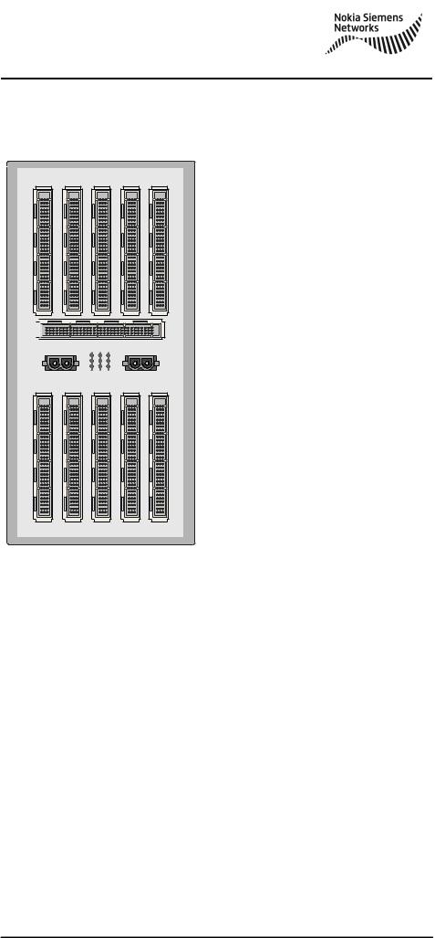
The following two figures show the rear sides of cartridges TC1C and
ET1TC with connector identifications.
JL1 |
|
|
|
|
|
|
|
|
|
|
|
|
|
|
|
PL4 |
|
|
|
|
|
|
|
|
|
|
|
|
|
|
|
R15 |
R14 |
R13 |
R12 |
R11 |
R10 |
R09 |
R08 |
R07 |
R06 |
R05 |
R04 |
R03 |
R02 |
R01 |
R00 |
|
S15 |
|
|
|
|
|
|
|
|
|
|
|
|
S00 |
|
|
|
|
|
|
|
|
|
|
|
|
|
|
|
|
1 |
PL3 |
|
|
|
|
|
|
|
|
|
|
|
|
|
|
|
PL2 |
|
|
|
|
|
|
|
|
|
|
|
|
|
|
5 |
|
|
|
|
|
|
|
|
|
|
|
|
|
|
|
6 |
|
|
|
|
|
|
|
|
|
|
|
|
|
|
|
7 |
PL1 |
|
|
|
|
|
|
|
|
|
|
|
|
|
|
|
DN9833788 |
|
|
|
|
|
|
|
|
|
|
|
|
|
|
|
Figure 19. Rear view of the TC1C with connector locations for interconnection cabling
DN0117872 |
# Nokia Siemens Networks |
55 (80) |
Issue 2-2 en |
|
|
TCSM2
R04 R03 R02 R01 R00
1
3
5
7
V00 


|
|
5 |
1 |
PL2 |
LL3 |
LL2 LL1 |
PL1 |
1
3
5
7
S04 |
S03 |
S02 |
S01 |
S00 |
DN9833776
Figure 20. Rear view of the ET1TC with connector positions for interconnection cabling
Interconnection of the TC1C and the ET1TC
An interconnection cable connects the data, clock, and alarm signals between the TC1C and ET1TC cartridges. Even numbers of the TCSM2A use the upper part of the ET1TC, and odd numbers the lower part. The table below presents the connections in detail. The connectors are 1/2- Euroconnectors.
56 (80) |
# Nokia Siemens Networks |
DN0117872 |
|
|
Issue 2-2 en |

TC1C and ET1TC cartridge intermediate cabling
Table 4. Connections for the TC1C - ET1TC interconnection cable
TCSM2A no. |
TC1C no. |
TC1C connector |
ET1TC |
|
|
position |
connector |
|
|
|
position |
|
|
|
|
0 |
0 |
S00-1 |
V00-5 |
(and other even |
(and other even |
|
|
numbers) |
numbers) |
|
|
|
|
|
|
1 |
1 |
S00-1 |
V00-1 |
(and other odd |
(and other odd |
|
|
numbers) |
numbers) |
|
|
|
|
|
|
Alarm bus
The alarm bus between the TCSM2As consists of a chain of cables. TC1C connector S00-6 of one TC1C is connected to the TC1C connector S00-5 of the next TC1C. The first TC1C of the chain has S00-5 empty, and the last TC1C has S00-6 empty. The connector of the cable is a 1/8- Euroconnector.
Alarm inputs
A connector is reserved for future use, to connect external wired alarms (a maximum of 3) to the TRCO through the TC1C back plane. It is a 1/8- Euroconnector in position S00-7.
Power supply cables for the TC1C
The cables for the duplicated power supply are connected to TC1C connectors PL1 and PL2, from the rack fuses.
Connectors PL3 and PL4 can be used to provide a parallel feeding of +5 V and -5 V voltages to and from the other cartridges. (Their use is an option for the future).
Power supply and grounding cables for the ET1TC
The table below shows the connections of the power supply cable at the ET1TC side. The other end is connected to the rack fuse outputs. The connector at the ET1TC side is a 1/4-Euroconnector.
DN0117872 |
# Nokia Siemens Networks |
57 (80) |
Issue 2-2 en |
|
|

TCSM2
Table 5. Connections of the power supply to the ET1TC
Part of ET1TC supplied |
Connector |
|
|
Upper |
PL1 |
|
|
Lower |
PL2 |
|
|
The overvoltage-protection return-current of the DS1-port is led by a cable from terminal LL2 to the rack ground busbar. It is also possible to connect the cables of different ET1TCs as a daisy chain, by using terminals LL2 and LL3.
58 (80) |
# Nokia Siemens Networks |
DN0117872 |
|
|
Issue 2-2 en |