

Материалы / Курсовые работы 2014 / Материалы для курсовых работ 2014 / K7_K8_ISO18000-6_2004
.pdf---`,,`,,`,`,,`-`-`,,,,,,--
ISO/IEC 18000-6:2004(E)
Table 8 — FHSS carrier rise and fall parameters
Parameter |
Min |
Max |
|
|
|
Tfhr |
|
30 µs |
|
|
|
Tfhs |
400 µs |
|
|
|
|
Tfhf |
|
30µs |
|
|
|
6.5FM0 return link
6.5.1FM0 return link general
The tag transmits information to the interrogator by modulating the incident energy and reflecting it back to the interrogator (backscatter).
6.5.2Modulation
The tag switches its reflectivity between two states. The “space” state is the normal condition in which the tag is powered by the interrogator and able to receive and decode the forward link. The “mark” state” is the alternative condition created by changing the antenna configuration or termination.
6.5.3Data rate
The data rate is 40kbit/s.
6.5.4Data coding
Data is coded using the FM0 technique, also known as Bi-Phase Space.
One symbol period Trlb, as specified in Table 9, is allocated to each bit to be sent. In FM0 encoding, data transitions occur at all bit boundaries. In addition, data transitions occur at the mid-bit of logic 0 being sent.
Table 9 — Return link parameters
Data rate |
Trlb |
Tolerance |
|
|
|
40kbit/s |
25 µs |
+/-15% |
|
|
|
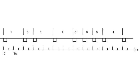
Coding of data is MSB first. Figure 7 illustrates the coding for the 8 bits of 'B1'.
Copyright International |
© ISO/IEC 2004 – All rights reserved |
13 |
|
Organization for Standardization |
|
Reproduced by IHS under license with ISO |
|
|
No reproduction or networking permitted without license from IHS |
Not for Resale |
|

ISO/IEC 18000-6:2004(E)
Figure 7 — Tag to interrogator data coding
6.5.5Message format
A return Link Message consists of n data bits preceded by the Preamble. The data bits are sent MSB first.
The Preamble enables the interrogator to lock to the tag data clock and begin decoding of the message. It consists of 16 bits as shown in Figure 8. There are multiple code violations (sequences not conforming to FM0 rules) that act as a frame marker for the transition from Preamble to Data.
6.5.6Return preamble
The return preamble is a sequence of backscatter modulation specified in Figure 8.
--`,,,,,,-`-`,,`,,`,`,,`---
NOTE |
The high state represents high reflectivity and the low state represents low reflectivity. |
Figure 8 — Preamble waveform
Changing the Tag’s modulator switch from the high impedance state to the low impedance state causes a change in the incident energy to be back-scattered, see Figure 9.
The tag shall execute backscatter, a half-low and half-high sent by the tag defined as follows:
Copyright 14 |
© ISO/IEC 2004 – All rights reserved |
International Organization for Standardization |
|
Reproduced by IHS under license with ISO |
|
No reproduction or networking permitted without license from IHS |
Not for Resale |

ISO/IEC 18000-6:2004(E)
Figure 9 — Return link bit coding
6.5.7Cyclic redundancy check (CRC)
6.5.7.1CRC General
Types A and B use the same CRC-16 for the forward and the return links. In addition, Type A uses CRC-5 for short commands when it satisfies the required level of protection against errors.
--`,,,,,,-`-`,,`,,`,`,,`---
On receiving a command from the interrogator, the tag shall verify that the checksum or the CRC value is valid. If it is invalid, it shall discard the frame, shall not respond and shall not take any other action.
6.5.7.2Interrogator to tag 5 bit CRC-5
The 5 bit CRC shall be calculated on all the command bits after the SOF up to but not including the first CRC bit.
The polynomial used to calculate the CRC is x5+x3+1.
A possible implementation is using a 5-bit shift register as defined in Clause A.1. The 5 bit CRC register is named Q4 to Q0, with Q4 being the MSB and Q0 being the LSB. The 5-bit register must be preloaded with '01001’ (MSB to LSB) or in hexadecimal notation 0x09 (HEX), as shown in Table A.1
The 11 bits of data must be clocked through the CRC register, using the MSB first. The 5 CRC bits are then sent, MSB first. After the LSB of the CRC-5 bit is clocked through, the 5-bit CRC register should contain all zero’s.
NOTE |
A schematic of a possible implementation is provided in Annex A. |
6.5.7.3Interrogator to tag 16 bit CRC-16
6.5.7.3.1Interrogator to tag CRC-16 general
The 16 bit CRC shall be calculated on all the command bits after the SOF up to but not including the first CRC bit.
The polynomial used to calculate the CRC is x16 + x12 + x5 + 1. The 16-bit register shall be preloaded with 'FFFF’. The resulting CRC value shall be inverted, attached to the end of the packet and transmitted.
The most significant byte shall be transmitted first. The most significant bit of each byte shall be transmitted first.
NOTE |
A schematic of a possible implementation is provided in Annex A. |
The CRC may be implemented in one of two ways:
Copyright International |
© ISO/IEC 2004 – All rights reserved |
15 |
|
Organization for Standardization |
|
Reproduced by IHS under license with ISO |
|
|
No reproduction or networking permitted without license from IHS |
Not for Resale |
|

ISO/IEC 18000-6:2004(E)
6.5.7.3.2Inversion of incoming CRC bits by the tag
At the tag, the incoming CRC bits are inverted and then clocked into the register. After the LSB CRC bit is clocked into the register the 16 bit CRC register should contain all zero’s.
6.5.7.3.3Non-inversion of incoming CRC bits by the tag
If the received CRC bits are not inverted before clocking into the register, then after the LSB CRC bit is clocked into the register the 16 bit CRC register will have the value 0x1D0F (HEX)
6.5.7.4Tag to interrogator 16 bit CRC-16
6.5.7.4.1Tag to interrogator to tag CRC-16 general
The 16 bit CRC shall be calculated on all data bits up to, but not including, the first CRC bit.
The polynomial used to calculate the CRC is x16 + x12 + x5 + 1. The 16-bit register shall be preloaded with 0xFFFF (HEX). The resulting CRC value shall be inverted, attached to the end of the packet and transmitted.
The most significant byte shall be transmitted first, see Table 10. The most significant bit of each byte shall be transmitted first.
On receiving of a response from the tag, it is recommended that the interrogator verifies that the CRC value is valid. If it is invalid, appropriate remedial action is the responsibility of the interrogator designer.
NOTE |
A schematic of a possible implementation is provided in Annex A. |
Table 10 — CRC-16 bits and bytes transmission rules
MSByte |
LSByte |
|
|
MSB LSB |
MSB LSB |
|
|
CRC-16 (8 bits) |
CRC-16 (8 bits) |
|
|
↑ first transmitted bit of the inverted CRC
The CRC may be implemented in one of two ways.
6.5.7.4.2Inversion of incoming CRC bits by the interrogator
At the reader receiver, the incoming CRC bits are inverted and then clocked into the register. After the LSB CRC bit is clocked into the register the 16 bit CRC register should contain all zero’s.
6.5.7.4.3Non-inversion of incoming CRC bits by the interrogator
If the received CRC bits are not inverted before clocking, the CRC register will have the value 0x1D0F (HEX).
|
--`,,,,,,-`-`,,`,,`,`,,`--- |
Copyright 16 |
© ISO/IEC 2004 – All rights reserved |
International Organization for Standardization |
|
Reproduced by IHS under license with ISO |
|
No reproduction or networking permitted without license from IHS |
Not for Resale |

ISO/IEC 18000-6:2004(E)
7 Type A
7.1Physical layer and data coding
7.1.1PIE (Pulse interval encoding) forward link
7.1.1.1Carrier modulation pulses
The data transmission from the interrogator to the tag is achieved by modulating the carrier amplitude (ASK). The data coding is performed by generating pulses at variable time intervals. The duration of the interval between two successive pulses carries the data coding information.
The tag shall measure the inter-pulse time on the high to low transitions (falling) edges of the pulse as shown in Figure 10.
The carrier modulation pulses are negative-going raised cosine shaped, their characteristics are specified in Figure 11 and Table 11.
Figure 10 — Inter-pulse mechanism
|
© ISO/IEC 2004 – All rights reserved |
--`,,,,,,-`-`,,`,,`,`,,`--- |
Copyright International |
17 |
|
|
Organization for Standardization |
|
Reproduced by IHS under license with ISO |
|
|
No reproduction or networking permitted without license from IHS |
Not for Resale |
|

ISO/IEC 18000-6:2004(E)
NOTE The vertical lines occur at the half power (3dB) point on the modulation carrier dip.
Figure 11 — Modulation shaping
Table 11 — Modulation parameters
Parameter |
Min |
Nominal |
Max |
|
|
|
|
Tapw |
|
10µs |
|
|
|
|
|
D |
27% |
|
See NOTE 2 |
|
See NOTE 1 |
|
|
|
|
|
|
Tapf |
|
4µs |
|
|
|
|
|
Tapr |
|
4µs |
|
|
|
|
|
Cht |
|
|
0.1 D |
|
|
|
|
Clt |
|
|
0.1 D |
|
|
|
|
NOTE 1 The minimum modulation depth value is the absolute limit over the interrogator's operating temperature range.
NOTE 2 The maximum modulation depth is may be in the range of 0.73 to 0 times the steady state value and will depend on the radio regulatory environment.
The interrogator shall maintain a constant modulation depth during the transmission of a command, within the Cht and Clt tolerances.
7.1.1.2Data coding and framing
The time Tari specifies the reference interval between the falling edges of two successive pulses representing the symbol '0' as transmitted by the interrogator; its value is specified in Table 12
International Organization for Standardization |
--`,,,,,,-`-`,,`,,`,`,,`--- |
|
|
Copyright 18 |
|
Reproduced by IHS under license with ISO |
|
No reproduction or networking permitted without license from IHS |
Not for Resale |
© ISO/IEC 2004 – All rights reserved

ISO/IEC 18000-6:2004(E)
Table 12 — Reference interval timing
Tari |
Tolerance |
|
|
20 µs |
± 100 ppm |
|
|
Four symbols are defined as shown as shown in Table 13 and Figure 12. The symbols are referenced to the interval Tari and have a duration of 1 Tari, 2 Tari, and 4 Tari being integer multiples of Tari and shall have a tolerance with respect to Tari as defined in Table 13. The Start of Frame, SOF symbol is a combinational symbol made up by concatenating a ‘0’ symbol with a symbol having a duration of 3 Tari, for an overall length of 4 Tari.
|
|
|
|
Table 13 — PIE symbols, coding |
|
|
|
|
|
|
|
-- |
|
Symbol |
|
Duration |
Tolerance with respect to 1 Tari |
-`-`,,,,,, |
|
|
|
|
|
0 |
|
1 |
Tari |
|
|
---`,,`,,`,`,,` |
|
|
|
|
|
1 |
|
2 |
Tari |
± 100 ppm |
|
|
|
||||
|
|
|
|
|
|
|
SOF |
|
1 |
Tari followed by |
± 100 ppm |
|
|
|
3 |
Tari |
|
|
|
|
|
|
|
|
EOF |
|
4 |
Tari |
± 100 ppm |
|
|
|
|
|
|
Figure 12 — PIE symbols
Copyright International |
© ISO/IEC 2004 – All rights reserved |
19 |
|
Organization for Standardization |
|
Reproduced by IHS under license with ISO |
|
|
No reproduction or networking permitted without license from IHS |
Not for Resale |
|

ISO/IEC 18000-6:2004(E)
7.1.1.3Decoding of PIE symbols by the tag
The tag shall be able to decode a PIE encoded transmission having symbols of duration as specified in Table 14:
Table 14 — Pie symbols, decoding
Symbol |
|
Mean duration |
Limits |
|
|
|
|
0 |
1 |
Tari |
1/2 Tari < ‘0’ ≤ 3/2 Tari |
|
|
|
|
1 |
2 |
Tari |
3/2 Tari < ’1’≤ 5/2 Tari |
|
|
|
|
SOF |
1 |
Tari followed by 3 |
Calibration sequence |
|
Tari |
|
|
|
|
|
|
EOF |
4 |
Tari |
W 4 Tari |
The reference for the decoder is derived from the SOF and is = 3/2 Tari
The tag shall interpret an interval between received symbols of >4 Tari as an EOF and shall discard the preceding data.
If the tag does not receive data for a period greater than EOF, the tag shall wait for a SOF.
7.1.1.4Frame format
The bits transmitted by the interrogator to the tag are embedded in a frame as specified in Figure 13.
Before sending the frame, the interrogator shall ensure that it has established an unmodulated carrier for a duration of at least Taq (Quiet time) of 300µs.
The frame consists of a Start Of Frame (SOF), immediately followed by the data bits and terminated by an End Of Frame (EOF). After having sent the EOF the interrogator shall maintain a steady carrier for the time specified by the protocol so that the tags are powered for transmitting their response.
If the tag does not receive data for a period greater than EOF, then the command decoder shall revert to the ready state and await another SOF.
The tag shall interpret an interval between received symbols of >4 Tari as an error and shall discard the preceding data.
20
Copyright International Organization for Standardization Reproduced by IHS under license with ISO
No reproduction or networking permitted without license from IHS
Figure 13 — Forward link frame format
--`,,,,,,-`-`,,`,,`,`,,`--- |
© ISO/IEC 2004 – All rights reserved |
|
|
|
Not for Resale |
ISO/IEC 18000-6:2004(E)
7.1.1.5Data decoding
The tag shall decode the symbols specified in Table 13.
The tag shall be able to decode an incoming signal having a modulation depth (as specified in clause 7.1.1.1, Figure 11 and Table 11) with respect to the reader steady state carrier of 27 % or greater (ie 27 % to 100 %). In other words the modulation depth may be anywhere in the range of 0.73 to 0 times the steady state carrier amplitude.
If the tag detects an invalid code, it shall discard the frame and wait for an unmodulated carrier of 4Tari duration.
7.1.1.6Bits and byte ordering
Coding of data into symbols shall be MSB first. The coding for the 8 bits of hex byte 'B1' is shown in Figure 14.
--`,,,,,,-`-`,,`,,`,`,,`---
Figure 14 — Example of PIE byte encoding for 'B1'
7.2Data elements
7.2.1Unique identifier (UID)
Tags may be uniquely identified in order to provide a one-to-one transaction between the tag and the interrogator and to provide traceability information relating to the transponder chip. When thus used, the tag Unique Identification number (UID) shall be in this form as specified in Table 15 and ISO/IEC 15963.
If used, the UID shall be set permanently by the IC manufacturer in accordance with Table 15.
Table 15 — UID format
MSB |
|
|
LSB |
|
|
|
|
b64 .. b57 |
b56 .. b49 |
b48 .. b33 |
b32 .. b1 |
|
|
|
|
‘E0' |
IC Mfg code |
RFU set to ‘0’ |
IC manufacturer serial number |
|
|
|
|
Copyright International |
© ISO/IEC 2004 – All rights reserved |
21 |
|
Organization for Standardization |
|
Reproduced by IHS under license with ISO |
|
|
No reproduction or networking permitted without license from IHS |
Not for Resale |
|

ISO/IEC 18000-6:2004(E)
The tag UID shall comprise
•The 8 MSB bits defined as 'E0',
•The IC manufacturer code of 8 bits according to ISO/IEC 7816-6, and
•A unique serial number of 48 bits assigned by the IC manufacturer.
7.2.2Sub-UID
When the Aloha protocol is used, only a part of the UID, called Sub-UID (SUID) is transmitted in most commands and in the tag response during a collision arbitration process. The only exception is the Get_system_information command that returns the complete UID of 64 bits. See clause 7.8.7.
The SUID consists of 40 bits: the 8 bits manufacturer code followed by the 32 LSBs of the serial number.
The 16 MSBs (bits 33 to 48) of the serial number shall be set to 0, as bits 33 to 48 are ignored in the SUID.
The mapping of the 64 bit UID to the transmitted 40 bits and back is described in Figure 15.
Figure 15 — UID/SUID mapping from 64 to 40
The interrogator shall use the 64-bit format specified in clause 7.2.1 when exchanging the UID with the application. It shall perform the required mapping described in Figure 15.
7.2.3Application family identifier
An Application Family Identifier (AFI) may optionally be used to group select tags. The AFI shall comprise a byte (8 bits). The AFI is a parameter in the Init_round command, or the first 8 bits in the selection mask of the Begin_round command.
Copyright 22 |
--`,,,,,,-`-`,,`,,`,`,,`--- |
© ISO/IEC 2004 – All rights reserved |
|
International Organization for Standardization |
|
Reproduced by IHS under license with ISO |
|
No reproduction or networking permitted without license from IHS |
Not for Resale |