

Cadence / DSD2 / Конспект -Введение в Cadence DSD2 / Конспект -Введение в Cadence DSD2 / Лекция2 / Parametric Analysis
.pdfParametric Analysis in Cadence Analog
Environment
Version 1.0
UCSN-0800-ZBT-14
August 2000
Z. Tao and M. Keramat
Analog & Mixed-Signal Laboratory
Department of Electrical & Computer Engineering
UNIVERSITY OF CONNECTICUT
Storrs, CT 06269-2157
E-mail: keramat@engr.uconn.edu
URL: http://www.engr.uconn.edu/~keramat/
Phone: (860) 486-5047
Fax: (860) 486-2447
Parametric Analysis in Cadence Analog
Environment
1. Introduction
This short tutorial aims at learning how to run parametric analysis with Cadence Analog Circuit Design Environment. As an example, a simple common source amplifier circuit is presented.
2. Procedures for Parametric Analysis
Step 1: > type “icms &”command to run Cadence under your working directory “~\cadence”.For( details, please refer to [1])
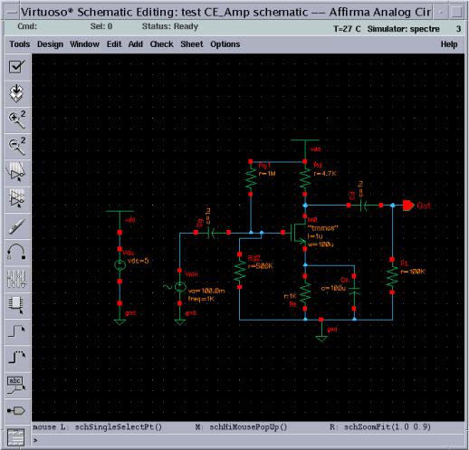
Step 2: open the cell named “CE_Amp” created in [2]. The circuit is shown in Fig. 1.
Fig. 1. The completed common source amplifier schematic.
- 1 -
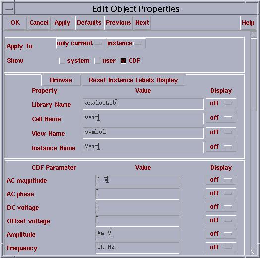
Step 3: highlight the component Vsin, and then go to Edit… Properties… Objects… set parameter “Am” for Amplitude property, as shown in Fig. 2.
Fig. 2. Properties of vsin.
Step 4: In “Virtuoso Schematic Editing” window, go to Tools… Analog Environment, an Affirma Analog Circuit Design Environment options form appears as Fig. 3.
- 2 -
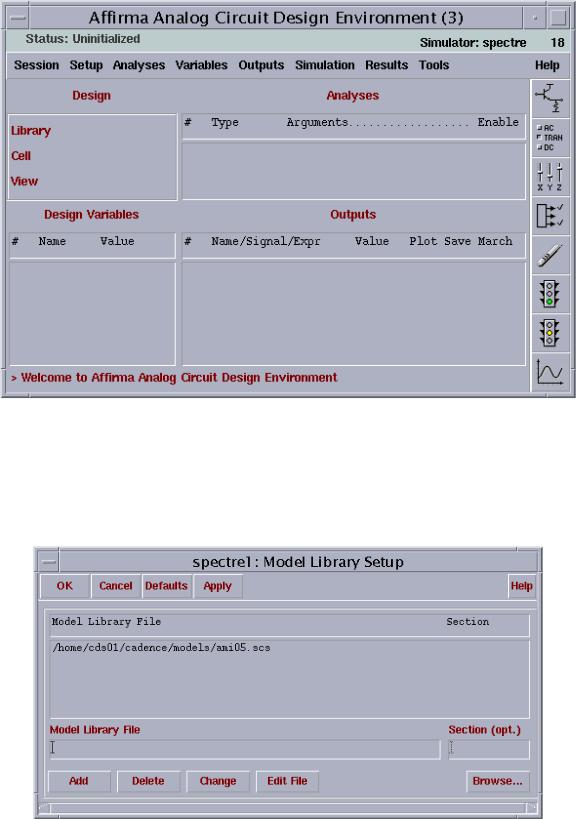
Fig. 3. Analog Artist Simulation window.
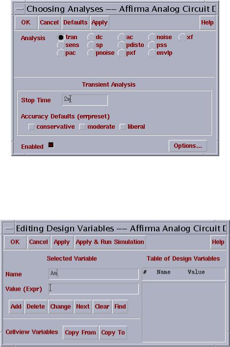
Step 5: In Affirma Analog Circuit Design Environment window, go to Setup… Model Libraries…, a Model Library Setup window appears. Choosing the model path in your home directory by clicking Browse…, then click Add, as Fig. 4.
Fig. 4. Adding model path.
- 3 -
Step 6: In Affirma Analog Circuit Design Environment window, go to Analysis… Choose…, and fill out the form according to Fig. 5, click Apply button.
Fig. 5. Transient analysis options form.
Step 7: In Affirma Analog Circuit Design Environment window, go to Variables … Edit… an Editing Design Variable options form appears as Fig. 6. Type “Am” in the Name space, and click OK button.
Fig. 6. Editing design variables form.
Step 8: In Affirma Analog Circuit Design Environment window, go to Outputs… To be Plotted… Select On Schematic. Then going back to the schematic window and selecting the wires attached to the In and Out. Note, the wires
- 4 -
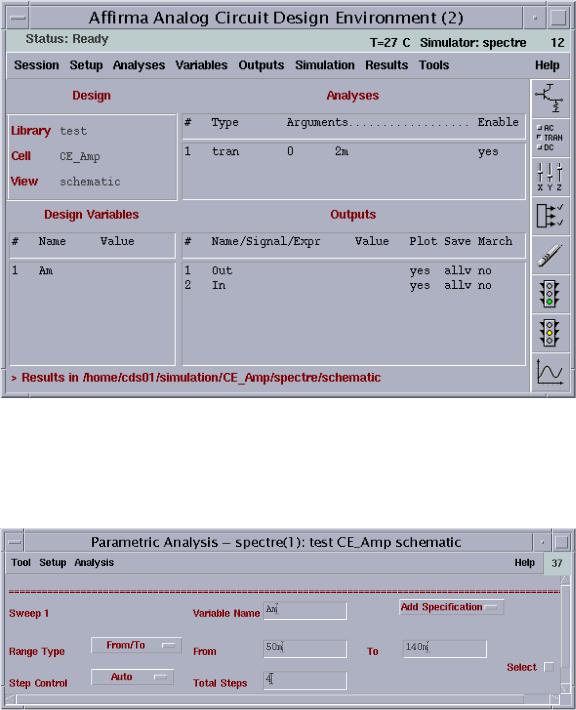
should change the color, and the signals should be added into the outputs window. The final Affirma Analog Circuit Design Environment option form should be as Fig. 7.
Fig. 7. Analog artist ready for parametric analysis.
Step 9: In Affirma Analog Circuit Design Environment window, go to Tools… Parametric Analysis... a form is popped up as Fig. 8. Fill out the form according to Fig. 8.
Fig. 8. Magnitude response of CE_Amp circuit.
- 5 -
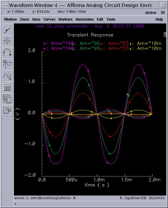
Step 10: In Parametric Analysis window, go to Analysis… Start. The simulation will be run automatically, and the result is shown in Fig. 9. It is seen that when the input signal amplitude is about 140 mV, the output will have a distortion.
Fig. 9. Transient response of CE_Amp circuit with different input amplitude.
- 6 -
Step 11: In Affirma Analog Circuit Design Environment window, go to Session… Save State…, then select OK.
Step 12: Exit the Affirma Analog Circuit Design Environment window, and exit the Virtuoso Schematic Editing window.
Step 13: In the CIW window, go to File… Exit.
3. Conclusions
Parametric analysis is a very important tool for circuit analysis, and it can help you to find and compare the effect of different parameter values on the circuit performance. For simplicity, a short tutorial on how to run parametric analysis with Cadence Affirma Analog Circuit Design Environment is presented. We try to include an example of a simple common source amplifier circuit and the effect of input signal amplitude on output distortion in this short tutorial, and it is helpful for beginners to further their jobs at a short time.
References
[1]Z. Tao and M. Keramat, “Short tutorial on cadence,” University of Connecticut, CT. No. UCSN-0300-ZBT-03, March 2000.
[2]Z. Tao and M. Keramat, “AC analysis in Cadence analog environment,” University of Connecticut, CT, No. UCSN-0800-ZBT-13, August 2000.
[3]Cadence Design Systems, Inc., Analog Artist Mixed-Signal Simulation and Analysis, 1999.
- 7 -