

About Subtractive Synthesis |
Page 81 |
When sync is applied, the basic pitch of Oscillator 2 is locked to that of Oscillator 1. If you change the pitch of Oscillator 1 you will affect the basic pitch of both oscillators. Furthermore, when you vary the pitch of the synchronized oscillator (Oscillator 2), this will be perceived as a change in timbre, rather than in pitch.
This leads to a spectrum with deep resonances at Osc2’s harmonics, like this:
Amplitude
Osc 2 Harmonics
Harmonic number
10 |
20 |
30 |
40 |
(Frequency) |
If you go even further and let the pitch of the synchronized oscillator vary continuously, for example from an LFO or envelope, you will change the harmonic content of the sound in an interesting and very characteristic way.
The Filter
The filter in a synthesizer is used to remove or emphasize frequencies in a spectrum. A filter is a bit like an amplifier (a volume control) that is applied differently to different parts of the spectrum. For example, a filter might make low frequencies louder, while at the same time making high frequencies weaker. Applying such a filter would make a sound have more bass and less treble.
Let’s imagine a sound with a spectrum where all harmonics are available at full level. It would look like this:
Let’s now pass this spectrum through a lowpass filter (this type of filter is discussed in more detail below). The filter has a characteristic, which can be drawn as a curve.
Page 82 |
About Subtractive Synthesis |
As you can see the curve is flat in the low register (which means it doesn’t affect this part of the spectrum at all) and then, at a certain point, gradually starts falling. When applied to the wave above, this filter cuts away some of the high frequency material in the wave, like this:
+ |
= |
Filter Types
There are many types of filters, all with their different purposes. We will here discuss the three most common, the ones found in the Nord Lead 2.
Lowpass filter: The Lowpass filter dampens high frequencies and let’s low frequencies pass through unaffected, as in the example above. It is the most common synthesizer filter, since it can be used to “round off” the sharp sound of sawtooth waves and pulse waves.
Amplitude
Fc (Cutoff Frequency)
 Frequency
Highpass Filter: This is the opposite of the lowpass filter. It let’s the high frequencies of the sound pass through and cuts off the low frequencies. This removes “bass” from a sound, without affecting the high end.
Amplitude
Fc (Cutoff Frequency)
 Frequency
About Subtractive Synthesis |
Page 83 |
Bandpass filter: This let’s frequencies in a certain range of the spectrum (the band) pass through while dampening frequencies both below and above this range. This accentuates the mid-range of a sound.
Amplitude
Fc (Cutoff Frequency)
 Frequency
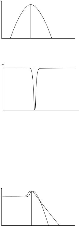
Notch filter: This filter type (also known as Band Reject) can be seen as the opposite of a band pass filter. It cuts off frequencies in a “mid-range” band, letting the frequencies below and above through.
Amplitude
Fc (Cutoff Frequency)
 Frequency
In the Nord Lead 2 the Notch filter is combined with a 12 dB Lowpass filter, for greater musical versatility (see page 44).
Roll-off
Filters of one and the same type (lowpass, highpass etc) can have different characteristics. One of the factors determining the exact filter curve is the roll-off, which is measured in dB/Octave (“decibels per octave”) or poles. The simplest possible filter has a roll-off of 6dB/octave, which is referred to as “1 pole”. The next step up is 12dB (2 poles), 18db (3 poles) etc.
The most common synth filters are the 12dB and 24dB lowpass filters. The difference between the two can be studied in the graph below. The 12dB filter let’s more of the high frequency pass through which gives the sound a brighter and “buzzier” character than the 24dB filter does.
Amplitude
Fc (Cutoff Frequency)
12dB (2-pole)
24dB (4-pole)
 Frequency
In the Nord Lead 2, the lowpass filter can be switched between 12 and 24dB modes. For sounds with high resonance (see below), similar to those in the Roland TB-303, we recommend the 12dB variation. For most other sounds we recommend 24dB.
Page 84 |
About Subtractive Synthesis |
Cutoff Frequency
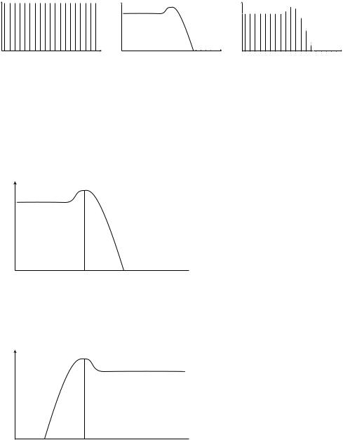
The most important parameter for a filter is its cutoff frequency, which is the setting that determines where in the frequency material it should start cutting. If the cutoff frequency in a low pass filter is set to a very low value, only the lowest harmonics (the bass) will pass through. If you raise the cutoff all the way up, all frequencies will be let through, as the figure below illustrates.
Amplitude
Filter Frequency
 Frequency
Changing the cutoff frequency is often referred to as “sweeping the filter”. This is probably one of the most important ways of shaping the timbre of a synthesizer sound. By using an envelope you can for example have a high cutoff at the beginning of a sound which is then gradually lowered (the filter “closes” as the sound decays). This would emulate the way most plucked string sound (piano, guitar etc) behave; the amplitude of the harmonics decreases as the sound decays.
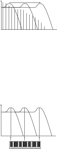
Key Tracking
When you play different pitches, the oscillators produce different frequencies. This means that the overtones in the waveform appear at different frequencies. The cutoff frequency of the filter however, is fixed. This means that different overtones will be cut off at different pitches. To be more precise, the further up the keyboard you play, the muddier the sound will be.
To remedy this problem many synthesizers have a parameter called Filter Keyboard Tracking. When this is activated, the filter Cutoff Frequency varies with which key you play, just as the oscillator frequency does. This ensures a constant harmonic spectrum for all keys.
Amplitude
 Frequency
Resonance
Resonance in a filter is created by connecting the output of the filter to its input, in other words setting up a “feedback loop”. The amount of feedback is then controlled with a Resonance parameter on the front panel of the instrument.
About Subtractive Synthesis |
Page 85 |
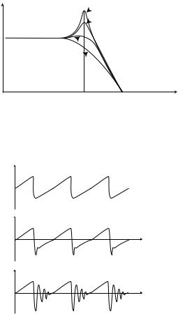
When you apply resonance, the frequencies just around the cutoff point of the filter will be emphasized (louder). As you increase the Resonance further and further, the filter will start to behave more an more like a bandpass filter, where only the frequencies around the cutoff point are let through. The filter will start to “ring”, which means it almost sounds like it is adding frequencies to the sound. If the Resonance is then raised even further (on some synthesizers) the filter will start to self-oscillate, that is produce sound of its own, just like an oscillator.
Amplitude |
Q=4 |
|
Q=2 |
Q=1
Q=0.5
Frequency
Filter
Frequency
High Resonance values are also visible in the waveform. They appear as a “superimposed” waveform with a frequency equivalent to the filter’s cutoff frequency. The three examples above show the same wave with increased resonance.
Q=0.5 
Q=1
Q=2
If you add Resonance to a sound and then vary the Cutoff frequency (for example with an envelope) you will get a very typical synthesizer sound.