

L3 / 03_Трещина
.pdfANSYS TUTORIAL { 2-D Fracture Analysis
ANSYS Release 7.0
Dr. A.-V. Phan, University of South Alabama
1Problem Description
Consider a nite plate in tension with a central crack as shown in Fig. 1. The plate is made of steel with Young's modulus E = 200 GPa and Poisson's ratio = 0:3. Let b = 0:2 m, a = 0:02 m,= 100 MPa. Determine the stress intensity factors (SIFs).
σ |
2a |
b |
Figure 1: Through-thickness crack.
Note that for this problem, tabulated solutions for the mode-I SIF KI are available in the literature. For example, an analytical solution given by W.D. Pilkey (Formulas for Stress, Strain,
and Structural Matrices) is |
|
|
|
p |
|
|
|
|
|
|
|
|
|
|
|
|
|
|
|
|
|
KI = C a ; |
||||
where |
|
|
|
|
|
|
|
|
|
|
(1 0:1 2 + 0:96 4)q |
|
; |
||||
C |
= |
1= cos( ) |
||||||
|
= |
|
a |
: |
|
|
|
|
|
b |
|
|
|
|
|||
|
|
|
|
|
|
|
|
|
Use of this solution yields KI = 25:680 MPa pm.
2Assumptions and Approach
2.1Assumptions
Linear elastic fracture mechanics (LEFM).
Plane strain problem.
1
2.2Approach
Since the LEFM assumption is used, the SIFs at a crack tip may be computed using the ANSYS's KCALC command. The analysis used a t of the nodal displacements in the vicinity of the crack tip (see the ANSYS, Inc. Theory Reference).
Due to the symmetry of the problem, only a quarter model is analyzed.
The crack-tip region is meshed using quarter-point (singular) 8-node quadrilateral elements (PLANE82).
3Preprocessing
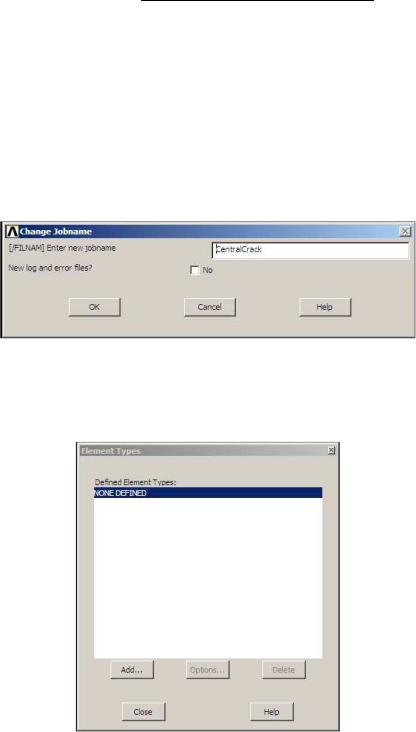
1.Give the Job a Name
Utility Menu > File > Change Jobname ...
The following window comes up. Enter a name, for example `CentralCrack', and click on
OK.
2.De ne Element Type
Main Menu > Preprocessor > Element Type > Add/Edit/Delete
This brings up the 'Element Types' window. Click on the Add... button.
The 'Library of Element Types' window appears. Highlight `Solid', and `8node 82', as shown. Click on OK.
2
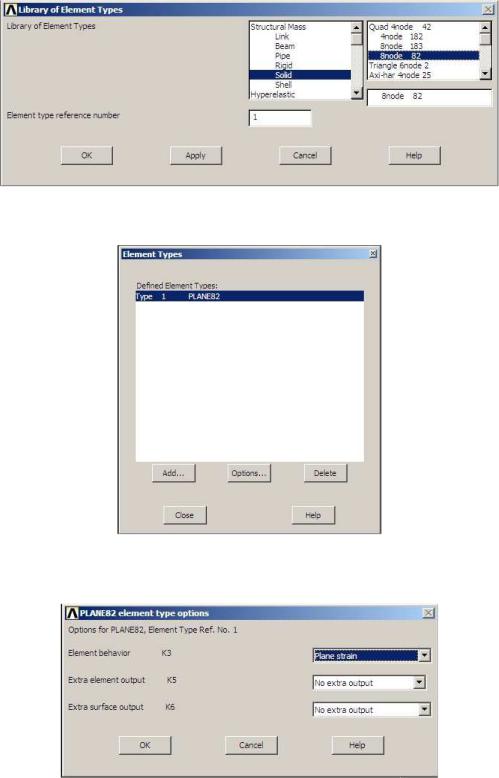
You should see `Type 1 PLANE82' in the `Element Types' window as follows:
Click on the Options... button in the above window. The below window comes up. Select `Plane strain' for `Element behavior K3' and click OK.
Click on the Close button in the `Element Types' window.
3.De ne Material Properties
Main Menu > Preprocessor > Material Props > Material Models
3
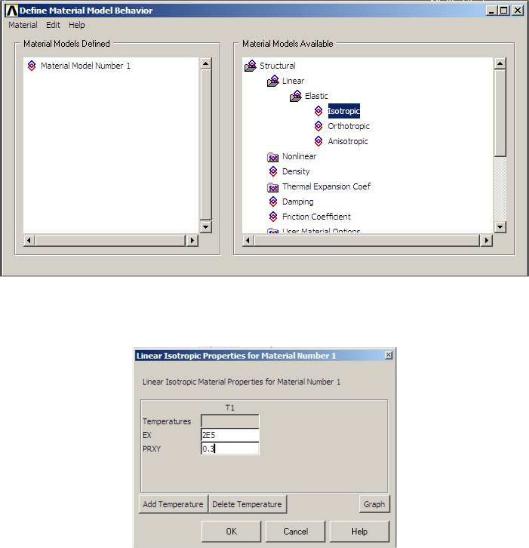
In the right side of the `De ne Material Model Behavior' window that opens, double click on `Structural', then `Linear', then `Elastic', then nally `Isotropic'.
The following window comes up. Enter in values for the Young's modulus (EX = 2E5) and Poisson's ratio (PRXY = 0.3) of the plate material.
Click OK, then close the `De ne Material Model Behavior' window.
4.De ne Keypoints
Main Menu > Preprocessor > Modeling > Create > Keypoints > In Active CS
We are going to create 5 keypoints given in the following table:
|
Keypoint # |
X |
Y |
|
|
|
|
|
1 |
0 |
0 |
|
2 |
0.02 |
0 |
|
3 |
0.1 |
0 |
|
|
|
|
|
4 |
0.1 |
0.1 |
|
5 |
0 |
0.1 |
|
|
|
|
4
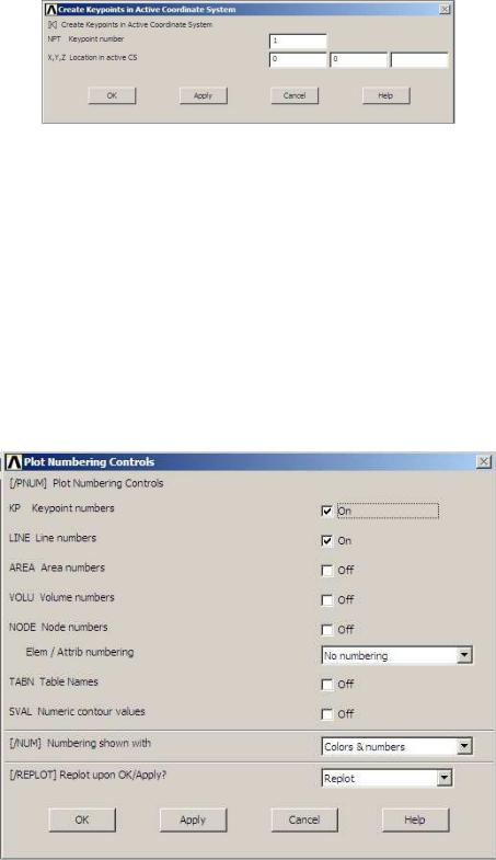
To create keypoint #1, enter `1' as keypoint number, and `0' and `0' as the X and Y coordinates in the following window. Click on Apply.
Repeat the above step for keypoints #2 through #5. Note that you must click on OK instead of Apply after entering data of the nal keypoint.
5.De ne Line Segments
Main Menu > Preprocessor > Modeling > Create > Lines > Lines > In Active Coord
Pick keypoint #1 then keypoint #2 to create a line connecting them (line #1).
Repeat the previous step to create lines connecting keypoints #2 and #3 (line #2), keypoints #3 and #4 (line #3), keypoints #4 and #5 (line #4), and keypoints #5 and #1 (line #5).
Click on OK to close the `Lines in Active Coord' window (picking window).
Turn on the numbering by selecting Utility Menu > PlotCtrls > Numbering .... The below window appears. Check the boxes for `Keypoint numbers' and `Line numbers' as shown, then click on OK.
5
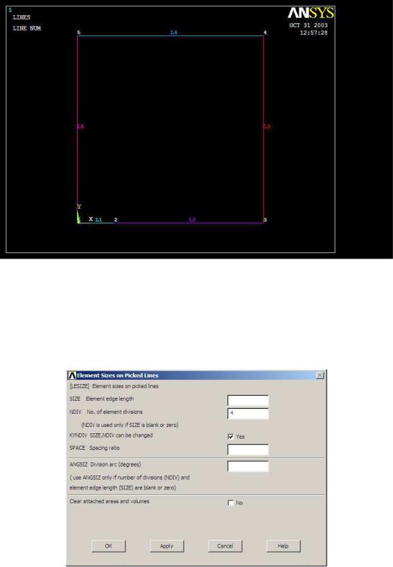
Select Utility Menu > Plot > Lines. Your graphics window should look like this,
6.Discretize Lines L3, L4 and L5
Main Menu > Preprocessor > Meshing > Size Cntrls > ManualSize > Lines > Picked
Lines
Pick lines #3 and #4. Click on the OK button in the picking window.
The below window opens. Enter `4' for 'No. of element divisions', then click Apply.
6
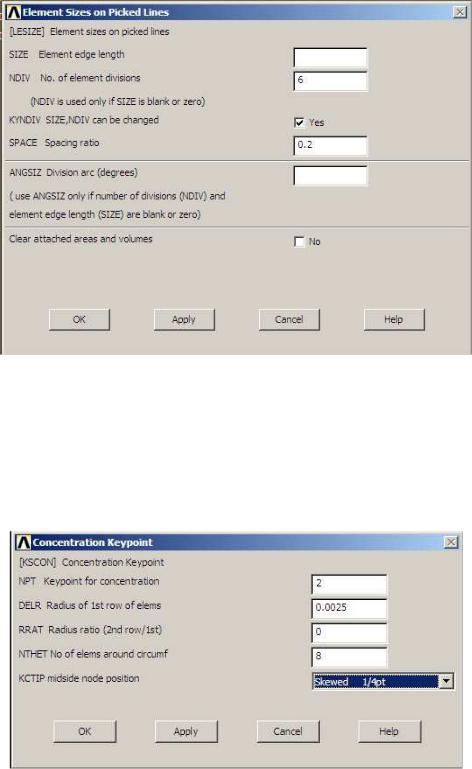
Pick line #5, then click OK in the picking window.
In the below window that comes up again, enter `6' for 'No. of element divisions', and `0.2' for `Spacing ratio', then click OK.
7.Create the Concentration Keypoint (Crack Tip)
Main Menu > Preprocessor > Meshing > Size Cntrls > Concentrat KPs > Create
Pick keypoint #2, then click OK in the picking window.
In the below window that appears, you should see `2' as `Keypoint for concentration'. Enter `0.0025' (= a=8) for `Radius of 1st row of elems', input `8' for `No of elems around circumf', and select `Skewed 1/4pt' for `midside node position'. Click OK.
7

8.Create the Area
Main Menu > Preprocessor > Modeling > Create > Areas > Arbitrary > By Lines
Pick all ve lines (L1 through L5). Click OK in the picking window.
9.Apply Boundary Conditions
Main Menu > Preprocessor > Loads > De ne Loads > Apply > Structural > Displacement > Symmetry B.C. > ...with Area
Pick line #2. Click Apply (in the picking window). Pick the area. Click Apply.
Pick line #5. Click Apply. Pick the area. Click OK.
10.Apply Loads
Main Menu > Preprocessor > Loads > De ne Loads > Apply > Structural > Pressure >
On Lines
Pick line #4. Click OK in the picking window.
In the below window that comes up, select `Constant value' for `Apply PRES on lines as a', enter `-100' for `Load PRES value', then click OK.
11.Mesh the Model
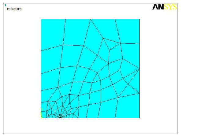
Main Menu > Preprocessor > Meshing > Mesh > Areas > Free
Pick the area. Click OK in the picking window.
Close the `Warning' window. In your ANSYS window, a mesh as shown at the top of next page should appear.
8
4Processing (Solving)
Main Menu > Solution > Analysis Type > New Analysis
Make sure that `Static' is selected. Click OK.
Main Menu > Solution > Solve > Current LS
Check your solution options listed in the `/STATUS Command' window.
Click the OK button in the `Solve Current Load Step' window.
Click the Yes button in the `Verify' window.
You should see the message `Solution is done!' in the `Note' window that comes up. Close the `Note' and `/STATUS Command' windows.
5Postprocessing
1.Zoom the Crack-Tip Region
Utility Menu > PlotCtrls > Pan Zoom Rotate ...
This brings up the following window:
9

In the above window, click on the Win Zoom button and zoom the crack-tip region, then click on the Close button to close the window.
Plot the nodes by selecting Utility Menu > Plot > Nodes.
Turn on the node numbering by selecting Utility Menu > PlotCtrls > Numbering
..., then check the box for `Node numbers', then nally click on OK. Your ANSYS Graphics windows should be similar to the following:
10