

151781-1CD
4.2 Manipulator Cable Connection
HP600 MANIPULATOR
A 

|
|
|
|
|
|
|
|
|
|
|
|
|
|
|
|
|
|
|
|
|
|
|
|
|
|
|
|
|
|
|
|
|
|
|
|
|
|
|
|
Bolt M8 for grounding |
|||
|
|
|
|
|
|
|
|
|
|
|
|
|
|
|
|
|
|
|
|
|
|
|
|
|
|
|
|
|
|
|
|
|
|
|
|
|
|
|
|
||||
|
|
|
|
|
|
|
|
|
|
|
|
|
|
|
|
|
|
|
|
|
|
|
|
|
|
|
|
|
|
|
|
|
|
|
|
|
|
|
|
||||
|
|
|
|
|
|
|
|
|
|
|
|
|
|
|
|
|
|
|
|
|
|
|
|
|
|
|
|
|
|
|
|
|
|
|
|
|
|
|
|
||||
|
|
|
|
|
|
|
|
|
|
|
|
|
|
|
|
|
|
|
|
|
|
|
|
|
|
|
|
|
|
|
|
|
|
|
|
|
|
|
|
||||
|
|
|
|
|
|
|
|
|
|
|
|
|
|
|
|
|
|
|
|
|
|
|
|
|
|
|
|
|
|
|
|
|
|
|
|
|
|
|
|
||||
|
|
|
|
|
|
|
|
|
|
|
|
|
|
|
|
|
|
|
|
|
|
|
|
|
|
|
|
|
|
|
|
|
|
|
|
|
|
|
|
||||
|
|
|
|
|
|
|
|
|
|
|
|
|
|
|
|
|
|
|
|
|
|
|
|
|
|
|
|
|
|
|
|
|
|
|
|
|
|
|
|
||||
|
|
|
|
|
|
|
|
|
|
|
|
|
|
|
|
|
|
|
|
|
|
|
|
|
|
|
|
|
|
|
|
|
|
|
|
|
|
|
|
||||
|
|
|
|
|
|
|
|
|
|
|
|
|
|
|
|
|
|
|
|
|
|
|
|
|
|
|
|
|
|
|
|
|
|
|
|
|
|
|
|
||||
|
|
|
|
|
|
|
|
|
|
|
|
|
|
|
|
|
|
|
|
|
|
|
|
|
|
|
|
|
|
|
|
|
|
|
|
|
|
|
|
||||
|
|
|
|
|
|
|
|
|
|
|
|
|
|
|
|
|
|
|
|
|
|
|
|
|
|
|
|
|
|
|
|
|
|
|
|
|
|
|
|
||||
|
|
|
|
|
|
|
|
|
|
|
|
|
|
|
|
|
|
|
|
|
|
|
|
|
|
|
|
|
|
|
|
|
|
|
|
|
|
|
|
||||
|
|
|
|
|
|
|
|
|
|
|
|
|
|
|
|
|
|
|
|
|
|
|
|
|
|
|
|
|
|
|
|
|
|
|
|
|
|
|
|||||
|
|
|
|
|
|
|
|
|
|
|
|
|
|
|
|
|
|
|
|
|
|
|
|
|
|
|
|
|
|
|
|
|
|||||||||||
|
|
|
|
|
|
|
|
|
|
|
|
8.0 mm2 or more |
|
|
|
|
|
|
|
|
|
|
|
|
(Delivered with the manipulator) |
||||||||||||||||||
|
|
|
|
|
|
|
|
|
|
|
|
|
|
|
|
|
|
|
|
|
|
|
|
|
|
|
|
|
|
|
|
|
|
|
|
|
|
|
|
View A |
|
||
|
|
|
|
|
|
|
|
|
|
|
|
|
|
|
|
|
|
|
|
|
|
|
|
|
Fig. 5 |
Grounding Method |
|||||||||||||||||
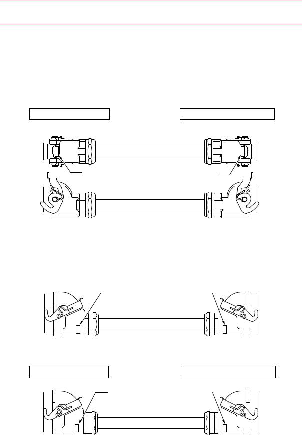
4.2Manipulator Cable Connection
There are three manipulator cables: 1BC, 2BC, and 3BC (Refer to " Fig. 6 Manipulator Cable Connections ".). Connect these cables to the connectors on the manipulator connector base and the NX100 respectively. For the details on connection, refer to " Fig. 7 (a) Details of the Manipulator Cable Connectors (Manipulator Side) " and " Fig. 7 (b) Manipulator Cable Connections to the NX100 ".
4.2.1Connection to the Manipulator
Before connecting the cables to the manipulator, verify the numbers on both manipulator cables and connectors on the manipulator connector base. When connecting, adjust the cable connector positions to the main key positions of the manipulator, and insert cables in the order of 2BC, 3BC, and 1BC and then set the lever down until it clicks.
4-2
HW0482904 21/73
151781-1CD
4.2 Manipulator Cable Connection
HP600 MANIPULATOR
4.2.2Connection to the NX100
Before connecting the cables to the NX100, verify the numbers on both manipulator cables and the NX100 board connectors. When connecting, adjust the cable connector positions to the main key positions of the NX100, and insert cables in the order of 2BC, 3BC, and 1BC and then set the lever down until it clicks.
Connection to the NX100
X11 |
X11 |
Connection to the Manipulator
1BC
Encoder Cable
1BC |
1BC
Connection to the NX100 |
|
Connection to the Manipulator |
|
|
|
X21
X21 |
2BC |
|
|
|
|
2BC
2BC
Power Cable
Connection to the NX100 |
Connection to the Manipulator |
X22 |
3BC |
|
3BC |
X22
3BC
Power Cable
Fig. 6 Manipulator Cable Connections
4-3
HW0482904 22/73

151781-1CD
4.2 Manipulator Cable Connection
HP600 MANIPULATOR
Key positions
Connector Details
(Manipulator Side)
Fig. 7 (a) Details of the Manipulator Cable Connectors (Manipulator Side)
X11
X21
X22
Fig. 7 (b) Manipulator Cable Connections to the NX100
4-4
HW0482904 23/73