


151781-1CD
3.1 Safeguarding Installation
HP600 MANIPULATOR
3.1Safeguarding Installation
To insure safety, be sure to install safeguarding. It prevent unforeseen accidents with personnel and damage to equipment. The following is quoted for your information and guidance.
Responsibility for Safeguarding [ISO 10218]
The user of a manipulator or robot system shall ensure that safeguards are provided and used in accordance with Sections 6, 7, and 8 of this standard. The means and degree of safeguarding, including any redundancies, shall correspond directly to the type and level of hazard presented by the robot system consistent with the robot application. Safeguarding may include but not be limited to safeguarding devices, barriers, interlock barriers, perimeter guarding, awareness barriers, and awareness signals.
3.2Mounting Procedures for Manipulator Baseplate
The manipulator should be firmly mounted on a baseplate or foundation strong enough to support the robot and withstand repulsion forces during acceleration and deceleration. Construct a solid foundation with the appropriate thickness to withstand maximum repulsion forces of the manipulator referring to " Table. 1 Maximum Repulsion Forces of the Manipulator ".
During installation, if the flatness is not right, the manipulator would be deformed and its functional ability may be compromised. The basplate flatness must be kept at 0.5 mm or less. Mount the baseplate in either way of the following: " 3.2.1 When the Manipulator and Mounting Fixture are Installed on a Baseplate " or " Fig. 4 Direct Mounting on the Floor ".
Table. 1 Maximum Repulsion Forces of the Manipulator
Maximum torque in horizontal rotation |
54000 N•m |
(S-axis moving direction) |
(5500 kgf•m) |
|
|
Maximum torque in vertical rotation |
88300 N•m |
(LU-axis moving direction) |
(9000 kgf•m) |
|
|
3-2
HW0482904 16/73
151781-1CD
3.2 Mounting Procedures for Manipulator Baseplate
HP600 MANIPULATOR
3.2.1When the Manipulator and Mounting Fixture are Installed on a Baseplate
The baseplate should be rugged and durable to prevent shifting of the manipulator or the mounting fixture. The thickness of the baseplate is 50 mm or more and a size of the anchor bolt of M24 or larger is recommended.
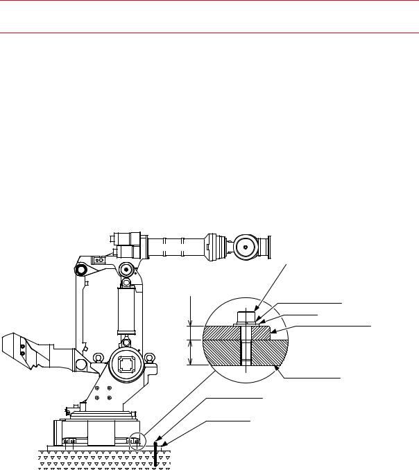
The manipulator is tapped for eight hexagon socket head cap screws M24. Fix the manipulator by fastening the manipulator base to the baseplate wtih eight hexagon socket head cap screws M24 (Tensile strength: 1200 N/mm2 or more) (Length: 80 mm is recommended). Tighten the screws to a tightening torque of 700 N•m (71 kgf•m). Tighten the screws and the anchor bolts securely so that they will not work loose during operation.
See " Fig. 3 Mounting the Manipulator on the Baseplate " for the method.
Hexagon socket head cap screw M24 (8 screws) (Tensile strength: 1200 N/mm2 or more) Tightening torque: 700 Nm (71 kgfm)
27 |
50 or more |
Spring washer Washer
Manipulator base
Baseplate
Anchor bolt
(M24 or larger)
Baseplate
Units: mm
Fig. 3 Mounting the Manipulator on the Baseplate
3-3
HW0482904 17/73
151781-1CD
3.2 Mounting Procedures for Manipulator Baseplate
HP600 MANIPULATOR
3.2.2When the Manipulator is Mounted Directly on the Floor
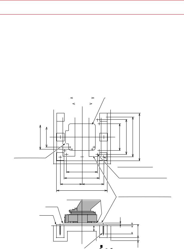
The floor should be strong enough to support the manipulator. Construct a solid foundation with the appropriate thickness to withstand maximum repulsion forces of the manipulator as shown in " Table. 1 Maximum Repulsion Forces of the Manipulator ". As a rough standard, when there is a concrete thickness (floor) of 250 mm or more, the base of the manipulator can be fixed directly to the floor with anchor bolts M24.
Before mounting the manipulator, however, check that the floor is level and that all cracks, etc. are repaired. Any thickness less than 250 mm is insufficient for mounting, even if the floor is concrete.
|
|
|
|
|
|
|
|
|
760 |
|
|
|
|
|
|
|
|
Tapped hole M24 (8 places) |
||||||||||
|
|
|
|
|
|
|
|
|
|
|
640 |
|
|
|
|
|
|
|
|
Bolt A |
||||||||
|
|
|
|
|
|
|
|
|
|
|
|
|
|
|
|
|
|
|
|
|
||||||||
|
|
|
|
|
|
|
|
|
|
|
|
|
|
|
|
|
|
|
|
|
|
|
|
|
|
|
|
|
|
|
|
|
|
|
|
|
|
|
|
|
|
|
|
|
|
|
|
|
|
|
|
|
|
|
|
|
|
|
|
|
|
|
|
|
|
|
|
|
|
|
|
|
|
|
|
|
|
|
|
|
|
|
|
|
|
|
|
|
|
|
|
|
|
|
|
|
|
|
|
|
|
|
|
|
|
|
|
|
|
|
|
|
|
|
|
|
|
|
|
|
|
|
|
|
|
|
|
|
|
|
|
|
|
|
|
|
|
|
|
|
|
|
|
|
|
|
|
|
|
|
|
|
|
|
|
|
|
|
|
|
|
|
|
|
|
|
|
|
|
|
|
|
|
|
|
|
|
|
|
|
|
|
|
|
|
|
|
|
|
|
|
|
|
|
|
|
|
|
|
|
|
|
|
|
|
|
|
|
|
|
|
|
|
|
|
|
|
|
|
|
|
|
|
|
|
|
|
|
|
|
|
|
|
|
|
|
|
|
|
|
|
|
|
|
|
|
|
|
|
|
|
|
|
|
|
|
|
|
|
|
|
|
|
|
|
|
|
|
|
|
|
|
|
|
|
|
|
|
|
|
|
|
|
|
|
|
|
|
|
|
|
|
|
|
|
|
|
|
|
|
|
|
|
|
|
|
|
|
|
|
|
|
|
|
|
|
|
|
|
|
|
|
|
|
|
|
|
|
|
|
|
|
|
|
|
|
|
|
|
|
|
|
|
|
|
|
|
760 |
640 |
Manipulator base
Base A
Base B
Perform leveling.
FL
850 |
1100 |
1250 |
1500 |
980
1100
685 685
1620
Manipulator base
 28 dia. hole (4 places) (Base B)
28 dia. hole (8 places) (Base A)
Tapped hole (8 places) (Base B)
Bolt B
Perform welding after
10  the adjusment for installation.
27 |
36 |
|
150 |
250 |
400 |
|
|
|
|
|
|
|
Foundation bolt M24, type-JA |
250 |
|
100 |
|||
|
||||||
(Length: 315) |
|
|
|
|
|
|
100
Bolt A: Anchor bolt M24 (8 bolts) (Length: 80) |
|
|
Spring washers, Flat washers |
|
|
Bolt B: Anchor bolt M24 (8 bolts) (Length: 75) |
|
|
Spring washers |
Units: mm |
|
Bolt A and B, and Base A and B are prepared by users. |
||
|
Fig. 4 Direct Mounting on the Floor
3-4
HW0482904 18/73