

151781-1CD
6.1 Allowable Wrist Load
HP600 MANIPULATOR
6Allowable Load for Wrist Axis and Wrist
Flange
6.1Allowable Wrist Load
The allowable wrist load is including the weight of mount/gripper is:
• YR-UP350N-A30, -A31 : 600 kg (at a maximum)
If force is applied to the wrist instead of the load, the force on R-, B-, and T-axes should be within the value shown in " Table. 4 Moment and Total Inertia ".
Table. 4 Moment and Total Inertia
Type |
Axis |
Moment N•m (kgf•m)*1 |
GD2/4 Total Inertia kg•m2 |
||
YR-UP350N-A30 |
R-axis |
2450 |
(250) |
200 |
|
B-axis |
2450 |
(250) |
200 |
||
YR-UP350N-A31 |
|||||
T-axis |
823 |
(84) |
90 |
||
|
|||||
|
|
|
|
|
|
*1 ( ): Gravitational unit
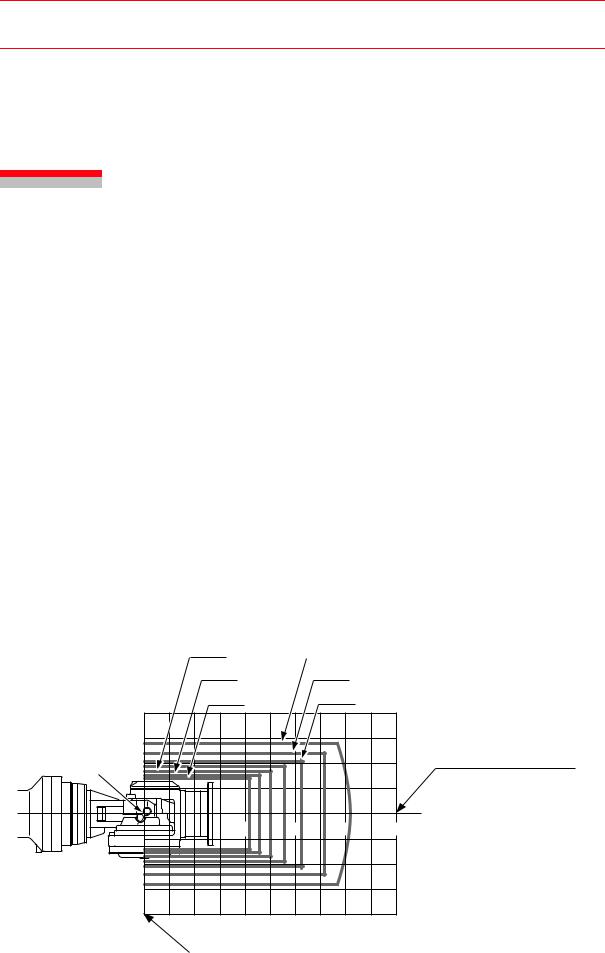
When the volume load is small, refer to the moment arm rating shown in " Fig. 11 Moment Arm Rating ".
The allowable total inertia is calculated when the moment is at its maximum. Contact your Yaskawa representative in advance in case if there is only inertia moment, or in case if load moment is small, yet inertia moment is large. Also, in the special case such as the load is combined as a force but a mass, contact your Yaskawa representative beforehand for further information or assistance.
|
500 kg |
|
350kg |
|
|
|
550 kg |
|
400 kg |
|
|
|
600 kg |
|
450 kg |
|
|
|
400 |
|
|
|
|
P-point |
200 |
|
|
|
Center of T- and R-axis rotation |
|
400 |
600 |
800 |
1000 |
LB (mm) |
|
200 |
|
|
|
|
|
400 |
|
|
|
|
|
LT (mm) |
|
|
|
|
Center of B-axis rotation
Fig. 11 Moment Arm Rating
6-1
HW0482904 28/73
151781-1CD
6.2 Wrist Flange
HP600 MANIPULATOR
6.2Wrist Flange
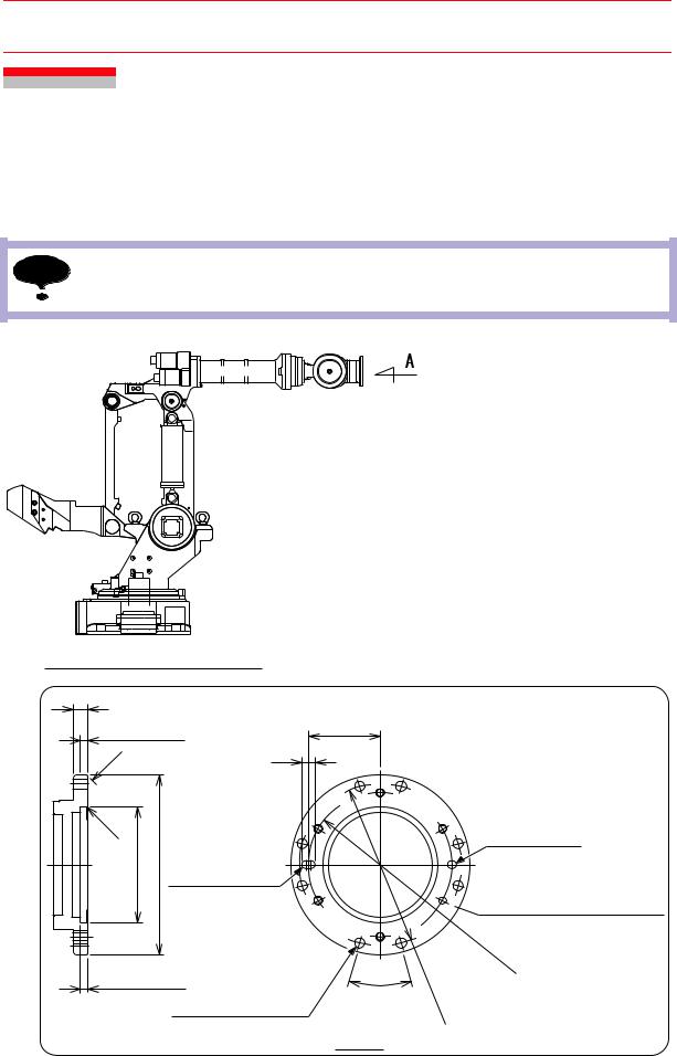
The wrist flange dimensions are shown in " Fig. 12 Wrist Flange ". In order to make the alignment marks visible, it is recommended that the attachment be mounted inside the fitting. Fitting depth of inside and outside fittings must be 8 mm or less.
NOTE |
Wash off anti-corrosive paint (solid color) on the wrist flange surface with thinner or light oil |
|
before mounting the tools. |
Manipulator in the Home Position
20
8 (Fitting depth) |
|
|
||
C1 |
|
|
|
18 |
|
|
|
|
|
C1 |
dia. |
|
|
|
dia. |
|
|
|
|
+0.063 0 |
0 -0.072 |
12 |
+ 0.018 |
dia. oval hole |
160 |
250 |
0 |
||
|
|
|
||
8 (Fitting depth) |
|
|
||
|
|
14 dia. hole |
||
|
|
(8 places, unequally-spaced) |
||
Fig. 12
100
30°
View A
Wrist Flange
12 |
+ 0.018 |
dia. hole |
0 |


 Tapped hole M12
(Pitch: 1.75) (6 holes, equalluy-spaced)
P.
C.
D.200
P . C . D . 225
Units: mm
6-2
HW0482904 29/73