

MOTOMAN-UP350N-600
INSTRUCTIONS
TYPE: YR-UP350N-A30 (UP350N-600)
YR-UP350N-A31 (UP350N-600 LU-AXES WITH LIMIT SWITCH SPEC)
Upon receipt of the product and prior to initial operation, read these instructions thoroughly, and retain for future reference.
MOTOMAN INSTRUCTIONS
MOTOMAN-UP350N-600 INSTRUCTIONS
NX100 INSTRUCTIONS
NX100 OPERATOR’S MANUAL
NX100 MAINTENANCE MANUAL
The NX100 operator’s manual above corresponds to specific usage.
Be sure to use the appropriate manual.
Part Number: 151781-1CD
Revision: 2
MANUAL NO.
HW0482904 7 1/73
151781-1CD
HP600 MANIPULATOR
 MANDATORY
•This instruction manual explains operating instructions and maintenance procedures primarily for the MOTOMAN-UP350N-600.
•General items related to safety are listed in Section 1: Safety of the NX100 Instructions. To ensure correct and safe operation, carefully read the NX100 Instruction before reading this manual.
 CAUTION
•Some drawings in this manual are shown with the protective covers or shields removed for clarity. Be sure all covers and shields are replaced before operating this product.
•The drawings and photos in this manual are representative examples and differences may exist between them and the delivered product.
•YASKAWA may modify this model without notice when necessary due to product improvements, modifications, or changes in specifications. If such modification is made, the manual number will also be revised.
•If your copy of the manual is damaged or lost, contact a YASKAWA representative to order a new copy. The representatives are listed on the back cover. Be sure to tell the representative the manual number listed on the front cover.
•YASKAWA is not responsible for incidents arising from unauthorized modification of its products. Unauthorized modification voids your product’s warranty.
ii
HW0482904 2/73
151781-1CD
HP600 MANIPULATOR
Notes for Safe Operation
Read this manual carefully before installation, operation, maintenance, or inspection of the MOTOMAN-UP350N-600.
In this manual, the Notes for Safe Operation are classified as “WARNING”, “CAUTION”, “MANDATORY”, or “PROHIBITED”.
 WARNING
  CAUTION
 MANDATORY
  PROHIBITED
Indicates a potentially hazardous situation which, if not avoided, could result in death or serious injury to personnel.
Indicates a potentially hazardous situation which, if not avoided, could result in minor or moderate injury to personnel and damage to equipment. It may also be used to alert against unsafe practices.
Always be sure to follow explicitly the items listed under this heading.
Must never be performed.
Even items described as “CAUTION” may result in a serious accident in some situations. At any rate, be sure to follow these important items.
NOTE |
To ensure safe and efficient operation at all times, be sure to follow all instructions, even if |
|
not designated as “CAUTION” and “WARNING”. |
iii
HW0482904 3/73
151781-1CD
HP600 MANIPULATOR
 WARNING
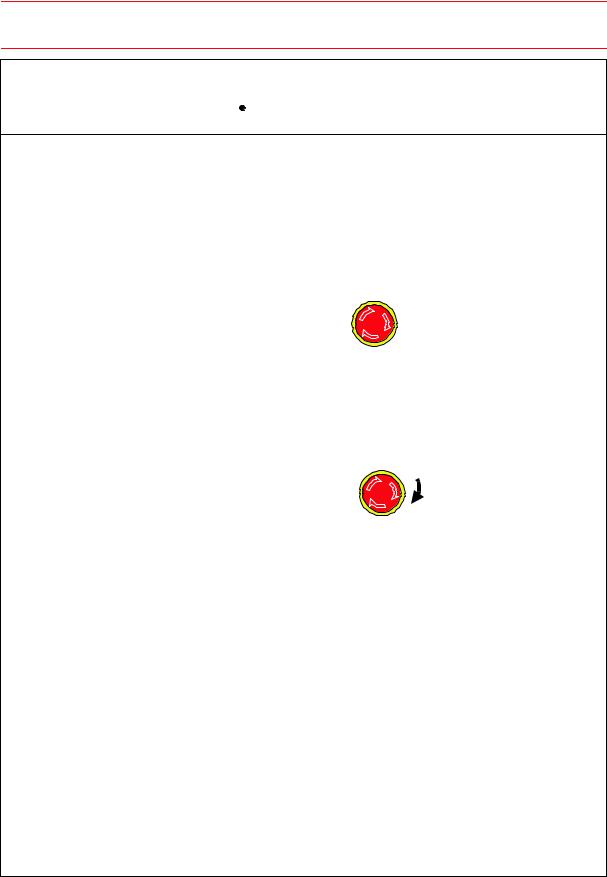
•Before operating the manipulator, check that servo power is turned OFF when the emergency stop buttons on the front door of the NX100 and programming pendant are pressed.
When the servo power is turned OFF, the SERVO ON LED on the programming pendant is turned OFF.
Injury or damage to machinery may result if the emergency stop circuit cannot stop the manipulator during an emergency. The manipulator should not be used if the emergency stop buttons do not function.
Emergency Stop Button
•Once the emergency stop button is released, clear the cell of all items which could interfere with the operation of the manipulator. Then turn the servo power ON.
Injury may result from unintentional or unexpected manipulator motion.

 TURN
TURN
Release of Emergency Stop
•Observe the following precautions when performing teaching operations within the P-point maximum envelope of the manipulator:
-View the manipulator from the front whenever possible.
-Always follow the predetermined operating procedure.
-Ensure that you have a safe place to retreat in case of emergency.
Improper or unintended manipulator operation may result in injury.
•Confirm that no person is present in the P-point maximum envelope of the manipulator and that you are in a safe location before:
-Turning ON the NX100 power.
-Moving the manipulator with the programming pendant.
-Running the system in the check mode.
-Performing automatic operations.
Injury may result if anyone enters the P-point maximum envelope of the manipulator during operation. Always press an emergency stop button immediately if there are problems. The emergency stop buttons are located on the right of the front door of the NX100 and programming pendant.
iv
HW0482904 4/73
151781-1CD
HP600 MANIPULATOR
 CAUTION
•Perform the following inspection procedures prior to conducting manipulator teaching. If problems are found, repair them immediately, and be sure that all other necessary processing has been performed.
-Check for problems in manipulator movement.
-Check for damage to insulation and sheathing of external wires.
•Always return the programming pendant to the hook on the NX100 cabinet after use.
The programming pendant can be damaged if it is left in the P-point maximum envelope of the manipulator, on the floor, or near fixtures.
•Read and understand the Explanation of Warning Labels in the NX100 instructions before operating the manipulator.
Definition of Terms Used Often in This Manual
The MOTOMAN manipulator is the YASKAWA industrial robot product.
The manipulator usually consists of the controller, the programming pendant, and supply cables.
In this manual, the equipment is designated as follows:
Equipment |
Manual Designation |
|
|
NX100 Controller |
NX100 |
|
|
NX100 Programming Pendant |
Programming Pendant |
|
|
Cables between the Manipulator and the NX100 |
Manipulator Cables |
Controller |
|
|
|
v
HW0482904 5/73
151781-1CD
HP600 MANIPULATOR
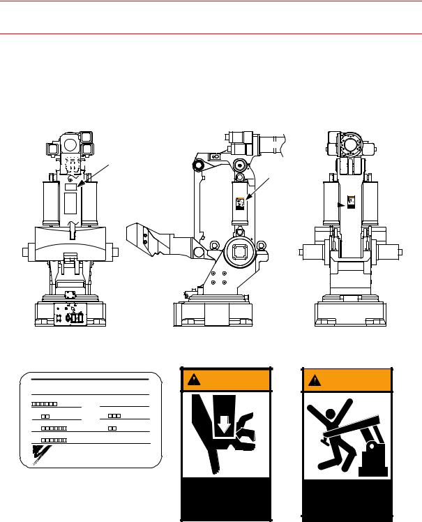
Explanation of Warning Labels
The following warning labels are attached to the manipulator. Always follow the warnings on the labels.
An identification label with important information is also placed on the body of the manipulator. Prior to operating the manipulator, confirm the contents.


 Nameplate
WARNING |
WARNING label B
 WARNING
WARNING label A 

Nameplate: |
WARNING label A: |
WARNING label B: |
MOTOMAN |
WARNING |
WARNING |
TYPE |
|
|
PAYLOAD |
MASS |
|
kg |
kg |
|
ORDER NO. |
DATE |
|
SERIAL NO. |
|
|
YASKAWA ELECTRIC CORPORAION JAPAN |
|
|
|
Moving parts |
Do not enter |
|
may cause |
robot |
|
injury |
work area. |
vi
HW0482904 6/73

151781-1CD
HP600 MANIPULATOR
1 Receiving
1.1 |
Contents Confirmation . . . . . . . . . . . . . . . . . . . . . . . . . . . . . |
1-1 |
1.2 |
Order Number Confirmation . . . . . . . . . . . . . . . . . . . . . . . |
1-2 |
2 Transporting
2.1 Transporting Method . . . . . . . . . . . . . . . . . . . . . . . . . . . . . . 2-1
2.1.1 Using a Crane . . . . . . . . . . . . . . . . . . . . . . . . . . . . . . . . . . . . . .2-2
2.2 Shipping Bolts and Brackets . . . . . . . . . . . . . . . . . . . . . . . 2-3
3 Installation |
|
|
3.1 |
Safeguarding Installation . . . . . . . . . . . . . . . . . . . . . . . . . . |
3-2 |
3.2 |
Mounting Procedures for Manipulator Baseplate . . . |
3-2 |
3.2.1 When the Manipulator and Mounting Fixture are Installed |
|
|
|
on a Baseplate. . . . . . . . . . . . . . . . . . . . . . . . . . . . . . . . . . . . . |
.3-3 |
3.2.2 When the Manipulator is Mounted Directly on the Floor . . . . . . |
3-4 |
|
3.3 |
Location . . . . . . . . . . . . . . . . . . . . . . . . . . . . . . . . . . . . . . . . . . . |
3-5 |
4 Wiring
4.1 |
Grounding . . . . . . . . . . . . . . . . . . . . . . . . . . . . . . . . . . . . . . . . . |
4-1 |
|
4.2 |
Manipulator Cable Connection. . . . . . . . . . . . . . . . . . . . . |
4-2 |
|
4.2.1 |
Connection to the Manipulator. . . . . . . . . . . . . . . . . . . . . . . . . |
.4-2 |
|
4.2.2 |
Connection to the NX100 . . . . . . . . . . . . . . . . . . . . . . . . . . . . . |
4-3 |
|
5 Basic Specifications
5.1 |
Basic Specifications . . . . . . . . . . . . . . . . . . . . . . . . . . . . . . . |
5-1 |
5.2 |
Part Names and Working Axes . . . . . . . . . . . . . . . . . . . . |
5-2 |
5.3 |
Manipulator Base Dimensions . . . . . . . . . . . . . . . . . . . . . |
5-2 |
5.4 |
Dimensions and P-Point Maximum Envelope . . . . . . |
5-3 |
5.5 |
Alterable S-axis Operating Range . . . . . . . . . . . . . . . . . |
5-4 |
vii
HW0482904 7/73

151781-1CD
HP600 MANIPULATOR
6 Allowable Load for Wrist Axis and Wrist Flange
6.1 Allowable Wrist Load . . . . . . . . . . . . . . . . . . . . . . . . . . . . . . . 6-1 6.2 Wrist Flange . . . . . . . . . . . . . . . . . . . . . . . . . . . . . . . . . . . . . . . 6-2
7 System Application
7.1 Peripheral Equipment Mounts . . . . . . . . . . . . . . . . . . . . . . 7-1 7.2 Internal User I/O Wiring Harness and Air Line . . . . . . 7-2
8 Motoman Construction
8.1 Position of S-axis Overrun Limit Switch. . . . . . . . . . . . . 8-1
8.2 Internal Connections . . . . . . . . . . . . . . . . . . . . . . . . . . . . . . . 8-1
9 Maintenance and Inspection
9.1 Inspection Schedule. . . . . . . . . . . . . . . . . . . . . . . . . . . . . . . . 9-1
9.2 Notes on Maintenance Procedures . . . . . . . . . . . . . . . . . 9-6
9.2.1 Battery Pack Replacement . . . . . . . . . . . . . . . . . . . . . . . . . . . . 9-6 9.2.2 Grease Replenishment/Exchange for S-axis
Speed Reducer. . . . . . . . . . . . . . . . . . . . . . . . . . . . . . . . . . . . . 9-8
Grease Replenishment (Refer to " Fig. 20 |
S-axis |
Speed Reducer and Gear Diagram ".) . . . |
. . . . . . . . . . . . . . 9-8 |
Grease Exchange (Refer to " Fig. 20 S-axis Speed |
|
Reducer and Gear Diagram ".) . . . . . . . . . . |
. . . . . . . . . . . . . 9-9 |
9.2.3 Grease Replenishment/Exchange for L- and U-axes |
|
Speed Reducers . . . . . . . . . . . . . . . . . . . . . . . |
. . . . . . . . . . . . 9-10 |
Grease Replenishment (Refer to " Fig. 21 |
LU-axis |
Speed Reducer Diagram ".) . . . . . . . . . . . . |
. . . . . . . . . . . . 9-10 |
Grease Exchange (Refer to " Fig. 21 LU-axis Speed |
|
Reducer Diagram ".) . . . . . . . . . . . . . . . . . . |
. . . . . . . . . . . . 9-11 |
9.2.4 Grease Replenishment/Exchange for R-axis |
|
Speed Reducer. . . . . . . . . . . . . . . . . . . . . . . . |
. . . . . . . . . . . . 9-12 |
Grease Replenishment (Refer to " Fig. 22 |
R-axis |
Speed Reducer Diagram ".) . . . . . . . . . . . . |
. . . . . . . . . . . . 9-12 |
Grease Exchange (Refer to " Fig. 22 R-axis Speed |
|
Reducer Diagram".) . . . . . . . . . . . . . . . . . . |
. . . . . . . . . . . . 9-13 |
9.2.5 Grease Replenishment/Exchange for B-axis Speed |
|
Reducer and Gear . . . . . . . . . . . . . . . . . . . . . |
. . . . . . . . . . . . 9-14 |
Grease Replenishment (Refer to " Fig. 23 |
B-axis |
Speed Reducer and Gear Diagram ".) . . . . |
. . . . . . . . . . . . 9-14 |
Grease Exchange (Refer to " Fig. 23 B-axis Speed |
|
Reducer and Gear Diagram ".) . . . . . . . . . . |
. . . . . . . . . . . . 9-15 |
viii
HW0482904 8/73

151781-1CD
HP600 MANIPULATOR
9.2.6 Grease Replenishment/Exchange for T-axis Speed |
|
Reducer and Gear . . . . . . . . . . . . . . . . . . . . . . . . . . . . . . . . . . |
9-16 |
Grease Replenishment (Refer to " Fig. 24 T-axis |
|
Speed Reducer and Gear Diagram ".) . . . . . . . . . . . . . . . . |
9-16 |
Grease Exchange (Refer to " Fig. 24 T-axis Speed |
|
Reducer and Gear Diagram ".) . . . . . . . . . . . . . . . . . . . . . . |
9-17 |
9.2.7 Grease Replenishment for S-axis Cross Roller Bearing . . . . . |
9-18 |
9.2.8 Grease Replenishment for L-axis Cross Roller Bearing . . . . . |
9-19 |
9.2.9 Grease Replenishment for Tapered Roller Bearing at |
|
Link and Connection . . . . . . . . . . . . . . . . . . . . . . . . . . . . . . . . |
9-20 |
9.2.10 Grease Replenishment for Balancer Connection . . . . . . . . . |
9-21 |
9.2.11 Notes for Maintenance . . . . . . . . . . . . . . . . . . . . . . . . . . . . . |
9-22 |
Battery Pack Connection for Motor . . . . . . . . . . . . . . . . . . . |
9-22 |
10Recommended Spare Parts
11Parts List
11.1 |
S-Axis Unit. . . . . . . . . . . . . . . . . . . . . . . . . . . . . . . . . . . . . |
. 11-1 |
11.2 |
L-Axis Unit . . . . . . . . . . . . . . . . . . . . . . . . . . . . . . . . . . . . . . |
11-3 |
11.3 |
Link Unit . . . . . . . . . . . . . . . . . . . . . . . . . . . . . . . . . . . . . . . . |
11-5 |
11.4 |
Balancer Unit* . . . . . . . . . . . . . . . . . . . . . . . . . . . . . . . . . . |
11-7 |
11.5 |
RBT-Axes Unit . . . . . . . . . . . . . . . . . . . . . . . . . . . . . . . . . . |
11-9 |
11.6 |
U-Axis Unit. . . . . . . . . . . . . . . . . . . . . . . . . . . . . . . . . . . . . |
11-11 |
11.7 |
Wrist Unit . . . . . . . . . . . . . . . . . . . . . . . . . . . . . . . . . . . . . . |
11-13 |
ix
HW0482904 9/73
151781-1CD
1.1 Contents Confirmation
HP600 MANIPULATOR
1 Receiving
 CAUTION
•Confirm that the order number of the manipulator and the NX100 are the same.
In case of installing more than one manipulator, pay special attention upon the number confirmation.
Failure to observe this caution may result in injury or damage.
1.1Contents Confirmation
Confirm the contents of the delivery when the product arrives.
Standard delivery includes the following four items (Information for the content of optional goods is given separately):
•Manipulator
•NX100
•Programming Pendant
•Manipulator Cables (3 cables, between the manipulator and the NX100)
1-1
HW0482904 10/73
151781-1CD
1.2 Order Number Confirmation
HP600 MANIPULATOR
1.2Order Number Confirmation
Check that the order number of the manipulator corresponds to the NX100. The order number is located on a label as shown below.
Label (Enlarged View)
THE MANIPULATOR AND THE CONTROLLER SHOULD HAVE SAME ORDER NUMBER.
ORDER NO. 


Check that the manipulator and the NX100 have the same order number.
NX100 |
****** |
|
|
|
|
|
|
|
|
|
|
ER GE NC |
|
|
|
|
|
|
E |
Y |
|
|
|
|
|
S |
T O P |
ORDER NO. |
|
|
|
|
|
|
|
WARNING |
|
|
|
|
|
Do not open the door |
|
|
|
|
|
|
|
X- |
X+ |
|
x |
x |
|
|
Y- |
Y+ |
|
y |
y |
|
|
- |
+ |
|
z |
z |
|
|
|
7 |
8 |
9 |
|
|
|
|
4 |
5 |
6 |
|
|
|
|
1 |
2 |
3 |
|
|
|
|
0 . |
- |
|
|
|
A 
View A
(a) NX100 (Front View) |
(b) Manipulator (Side View) |
Fig. 1 Location of Order Number Labels
1-2
HW0482904 11/73