

2 |
ERwin Methods Guide |
|
|
The Entity-Relationship Diagram
If you are familiar with a relational database structure, you know that the most fundamental component of a relational database is the table. Tables are used to organize and store information. A table is organized in columns and rows of data. Each row contains a set of facts called an instance of the table.
In a relational database, all data values must also be atomic — each cell in the table can contain only a single fact. There is also a relationship between the tables in the database. Each relationship is represented in an RDBMS by sharing one or more columns in two tables.
Like the tables and columns that make up a physical model of a relational database, an entity-relationship diagram (and all other logical data models) include equivalent components that let you model the data structures of the business, rather than the database management system. The logical equivalent to a table is an entity, and the logical equivalent to a column is an attribute.
In an ERD, the entity is represented by drawing a box that contains the with the name of the entity. Entity names are always singular — CUSTOMER not CUSTOMERS, MOVIE not MOVIES, COUNTRY not COUNTRIES. By always using singular nouns, you gain the benefit of a consistent naming standard and facilitate “reading” the diagram as a set of declarative statements about entity instances.
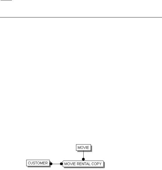
The diagram below is one created by a hypothetical video store that needs to track its customers, movies that can be rented or purchased, and rental copies of movies that are in stock in the store.
Sample Entity-Relationship Diagram
Relationships between tables are a vital component of a relational database. These relationships are captures using shared key: facts in one table refer to, or are associated with, facts in another table. In an ERD, a relationship is represented by a line drawn between the entities in the model. A relationship between two entities also implies that facts in one entity refer to, or are associated with, facts in another entity.
20 ∙ Constructing a Logical Model
ERwin Methods Guide |
2 |
|
|
In the example above, the video store needs to track information CUSTOMERs and MOVIE RENTAL COPYs. The information in these two entities is related, and this relationship can be expressed in a statement: A CUSTOMER rents one or more MOVIE RENTAL COPYs.
Defining Entities and Attributes
We can define an entity as any person, place, thing, event, or concept about which information is kept. More precisely, we can think of an entity as a set or collection of like individual objects called instances. An instance is a single occurrence of a given entity. Each instance must have an identity distinct from all other instances.
In the previous example, we might say that the CUSTOMER entity represents the set of all of the possible customers of a business. Each instance of the CUSTOMER entity is a customer. You can list information for an entity in a sample instance table, such as the one shown below.
CUSTOMER
customer-id |
customer-name |
customer-address |
10001 |
Ed Green |
Princeton, NJ |
10011 |
Margaret Henley |
New Brunswick, NJ |
10012 |
Tomas Perez |
Berkeley, CA |
17886 |
Jonathon Walters |
New York, NY |
10034 |
Greg Smith |
Princeton, NJ |
Sample Instance Table for the CUSTOMER Entity
Each instance represents a set of “facts” about the related entity. In the sample above, each instance of the CUSTOMER entity includes information on the “customer-id,” “customer-name,” and “customer-address.” In a logical model, these properties are called the attributes of an entity. Each attribute captures a single piece of information about the entity.
Constructing a Logical Model ∙ 21
2 |
ERwin Methods Guide |
|
|
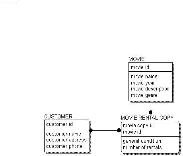
You can include attributes in an ERD to more fully describe the entities in the model, as shown below:
ERD With Attributes
Logical Relationships
Relationships represent connections, links or associations between entities. They are the “verbs” of a diagram showing how entities relate to each other. Easy-to-understand rules help business professionals validate data constraints, and ultimately identify relationship cardinality.
Here are some examples:
♦A TEAM <has> many PLAYERs.
♦A PLANE-FLIGHT <transports> many PASSENGERs.
♦A DOUBLES-TENNIS-MATCH <requires> exactly 4 PLAYERs.
♦A HOUSE <is owned by> one or more OWNERs.
♦A SALESPERSON <sells> many PRODUCTs.
In all of these cases, the relationships are chosen so that the connection between the two entities is what is known as 1-to-many. This means that one (and only one instance) of the first entity is related or connected to many instances of the second entity. The entity on the “1-end” is called the parent entity, the entity on the “many-end” is called the child entity.
22 ∙ Constructing a Logical Model
ERwin Methods Guide |
2 |
|
|
Relationships are displayed as a line connecting two entities, with a dot on one end, and a verb phrase written along the line. In the previous examples, the verb phrases are the words inside the brackets (e.g., <sells>). Here is a diagram of the relationship between PLANE-FLIGHTs and PASSENGERs on that flight.
Relationship Example
Many-to-Many Relationships
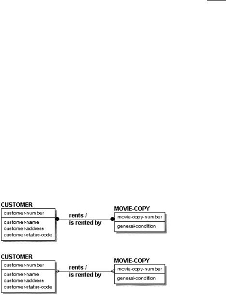
A many-to-many relationship, also called a non-specific relationship, represents a situation where an instance in one entity relates to one or more instances in a second entity, and an instance in the second entity also relates to one or more instances in the first. In the video store example, a many-to-many relationship occurs between a CUSTOMER and a MOVIE COPY. From a conceptual point of view, this many-to-many relationship indicates that “A CUSTOMER <rents> many MOVIE COPYs” and “A MOVIE COPY <is rented by> many CUSTOMERs.”
Example of a Many-to-Many Relationship in IDEF1X (top) and IE (bottom)
Many-to-many relationships tend to be used in a preliminary stage of diagram development, such as in an entity-relationship diagram (ERD) and are represented in IDEF1X as a solid line with dots on both ends.
Because a many-to-many relationship can hide other business rules or constraints, they should be fully explored at some point in the modeling process. For example, sometimes a many-to-many relationship identified in early modeling stages is mislabeled, and is actually two one-to-many
Constructing a Logical Model ∙ 23