- •GENERAL INFORMATION
- •DISTRIBUTOR CAP
- •ROTOR
- •SPARK PLUG CABLES
- •SPARK PLUGS
- •SPARK PLUG CONDITION
- •CABLE RESISTANCE CHART
- •SPARK PLUG SERVICE
- •ENGINE CONTROLLER
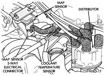
- •COOLANT TEMPERATURE SENSOR
- •MANIFOLD ABSOLUTE PRESSURE (MAP) SENSOR
- •AUTO SHUTDOWN (ASD) RELAY AND FUEL PUMP RELAY
- •IGNITION COIL
- •GENERAL INFORMATION
- •SPARK PLUGS
- •IGNITION COIL
- •COIL RESISTANCE
- •TESTING FOR SPARK AT COIL
- •POOR PERFORMANCE TEST
- •COOLANT TEMPERATURE SENSOR TEST
- •MANIFOLD ABSOLUTE PRESSURE (MAP) SENSOR TEST
- •DETONATION (KNOCK) SENSOR
- •ENGINE CONTROLLER
- •REMOVAL
- •INSTALLATION
- •COOLANT TEMPERATURE SENSOR
- •REMOVAL
- •INSTALLATION
- •REMOVAL
- •INSTALLATION
- •REMOVAL
- •INSTALLATION
- •SPARK PLUG SERVICE
- •SPARK PLUG REMOVAL
- •SPARK PLUG GAP ADJUSTMENT
- •IDLE SPECIFICATIONS
- •IDLE SPECIFICATIONS
- •IDLE SPECIFICATIONS
- •REMOVAL
- •INSTALLATION
- •REMOVAL
- •INSTALLATION
- •REMOVAL
- •INSTALLATION
- •DISASSEMBLY
- •GENERAL INFORMATION
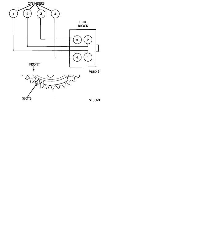
- •FIRING ORDER
- •ENGINE CONTROLLER
- •SPARK PLUG CABLES
- •SPARK PLUGS
- •SPARK PLUG CONDITION
- •CAMSHAFT REFERENCE SENSOR
- •CRANKSHAFT TIMING SENSOR
- •IGNITION COIL
- •COOLANT TEMPERATURE SENSOR
- •MANIFOLD ABSOLUTE PRESSURE (MAP) SENSOR
- •FAILURE TO START TEST
- •COOLANT TEMPERATURE SENSOR TEST
- •MANIFOLD ABSOLUTE PRESSURE (MAP) SENSOR TEST
- •CRANKSHAFT SENSOR AND CAMSHAFT SENSOR TESTS
- •ENGINE CONTROLLER
- •REMOVAL
- •INSTALLATION
- •REMOVAL
- •INSTALLATION
- •REMOVAL
- •INSTALLATION
- •REMOVAL
- •INSTALLATION
- •SPARK PLUG CABLE SERVICE
- •SPARK PLUG SERVICE
- •SPARK PLUG REMOVAL
- •SPARK PLUG GAP ADJUSTMENT
- •IDLE RPM TEST
- •CABLE RESISTANCE CHART
- •IGNITION TIMING PROCEDURE
- •REMOVAL
- •INSTALLATION
- •REMOVAL
- •INSTALLATION
- •REMOVAL
- •INSTALLATION
- •REMOVAL
- •INSTALLATION
- •IGNITION SWITCH
- •IGNITION SWITCH AND KEY CYLINDER SERVICE
- •REMOVAL
- •IGNITION SWITCH DESIGNATIONS
- •INSTALLATION
- •SPECIFICATIONS
- •GENERAL INFORMATION
- •DISTRIBUTORS
- •IGNITION COILS
- •SPARK PLUGS
- •TORQUE

8D - 26 IGNITION SYSTEMS |
|
Ä |
|
Fig. 40 Manifold Absolute Pressure (MAP)
SensorÐ3.0L Engine
TURBO III, 3.L AND 3.8L IGNITION SYSTEMÐSYSTEM OPERATION
INDEX
|
page |
Auto Shutdown (ASD) Relay and Fuel Pump |
|
Relay . . . . . . . . . . . . . . . . . . . . . . . . . . . . . . . |
. 35 |
Camshaft Reference Sensor . . . . . . . . . . . . . . . . |
. 30 |
Coolant Temperature Sensor . . . . . . . . . . . . . . . |
. 34 |
Crankshaft Timing Sensor . . . . . . . . . . . . . . . . . |
. 32 |
Detonation Sensor (Knock Sensor)ÐTurbo III |
|
Engine . . . . . . . . . . . . . . . . . . . . . . . . . . . . . . |
. 34 |
GENERAL INFORMATION |
|
This section describes the ignition systems for |
|
Turbo III, 3.3L and 3.8L engines. |
|
The Fuel Injection sections of Group 14 describe On |
|
Board Diagnostics. |
|
Group 0, Lubrication and Maintenance, contains |
|
general maintenance information for ignition related |
|
items. The Owner's Manual also contains mainte- |
|
nance information. |
|
Turbo III, 3.3L and 3.8L engines uses a fixed ignition timing system. Basic ignition timing is not adjustable. All spark advance is determined by the engine controller.
The ignition system does not use a distributor. The system is referred to as the Direct Ignition System. The system's three main components are the coil pack, crankshaft timing sensor, and camshaft reference sensor. The crankshaft and camshaft sensors are hall effect devices.
The camshaft and crankshaft sensors generate pulses that are the inputs sent to the engine controller. The engine controller interprets crankshaft and camshaft positions from these sensors. The engine
|
page |
Engine Controller . . . . . . . . . . . . . . . . . . . . . . . . |
. 26 |
General Information . . . . . . . . . . . . . . . . . . . . . . |
. 26 |
Ignition Coil . . . . . . . . . . . . . . . . . . . . . . . . . . . . |
. 33 |
Manifold Absolute Pressure (MAP) Sensor . . . . . |
. 34 |
Spark Plug Cables . . . . . . . . . . . . . . . . . . . . . . . |
. 28 |
Spark Plugs . . . . . . . . . . . . . . . . . . . . . . . . . . . . |
. 28 |
controller uses crankshaft position reference to determine ignition timing. The controller determines injector sequence from the camshaft position reference.
The camshaft sensor senses when a slot in the camshaft gear passes beneath it (Fig. 1 or Fig. 2). The crankshaft sensor senses when a window in the drive plate passes under it (Fig. 3 or Fig. 4). When a slot or window is sensed, the input voltage from the sensor to the engine controller switches from low (less than
.3 volts) to high (5 volts). As the slot or window passes, the input voltage is switched back to low (less than .3 volts).
FIRING ORDER
The firing order of the Turbo I engine direct ignition system is 1-3-4-2 (Fig. 5). The firing order of the 3.3L and 3.8L engines direct ignition system is 1-2-3-4-5-6 (Fig. 6).
ENGINE CONTROLLER
The ignition system is regulated by the Single board Engine Controller II (SBEC II), referred to in this manual as the Engine Controller (Fig. 7).
The controller supplies battery voltage to the igni-

Ä |
|
IGNITION SYSTEMS 8D - 27 |
|
Fig. 3 DriveplateÐTurbo III Engine
Fig. 1 Camshaft SprocketÐTurbo III Engine
Fig. 4 DriveplateÐ3.3L and 3.8L Engines
Fig. 2 Camshaft SprocketÐ3.3L and 3.8L Engines
tion coil through the Auto Shutdown (ASD) Relay. The controller also controls ground circuit for the ignition coil. By switching the ground path for the coil on and off, the engine controller adjusts ignition timing to meet changing engine operating conditions.
During the crank-start period the controller advances ignition timing a set amount. During engine operation, the amount of spark advance provided by the engine controller is determined by these input factors:
²coolant temperature
²detonation sensor (Turbo III)
Fig. 5 Spark Plug Wire RoutingÐTurbo III Engine
²engine RPM
²available manifold vacuum
The engine controller also regulates the fuel injection system. Refer to the Fuel Injection sections of Group 14.
