


Ä |
|
IGNITION SYSTEMS 8D - 15 |
|
Fig. 3 Coolant Temperature SensorÐ3.0L Engine
IGNITION COILÐ2.2L TBI, 2.5L TBI AND TURBO I ENGINES
The ignition coil mounts to the thermostat housing (Fig. 4).
Fig. 4 Ignition CoilÐ2.2L TBI, 2.5L TBI and Turbo I
Engines
REMOVAL
(1)Disconnect the coil to distributor ignition cable (Fig. 4).
(2)Disconnect the wiring harness connector from the coil.
(3) Remove ignition coil mounting screws.
INSTALLATION
(1)Install ignition coil onto the bracket. Tighten the screws to 9.5 NIm (85 in. lbs.) torque.
(2)Connect the wiring harness connector.
(3)Connect the coil to distributor ignition cable.
IGNITION COILÐ3.0L ENGINES
The ignition coil is located at the back of the intake manifold (Fig. 5).
Fig. 5 Ignition CoilÐ3.0L Engine
REMOVAL
(1)Remove air cleaner assembly.
(2)Disconnect ignition cable from coil.
(3)Disconnect wiring harness connector from coil.
(4)Remove coil mounting screws.
INSTALLATION
(1)Loosely install ignition coil on intake manifold. Tighten the intake manifold fastener to 13 NIm (115
in. lbs.) torque. Tighten ignition coil bracket fasteners to 10 NIm (96 in. lbs.) torque.
(2)Connect the wiring harness connector.
(3)Connect the coil to distributor ignition cable.
(4)Install the air cleaner assembly. Tighten the air cleaner fasteners to 25 NIm (225 in. lbs.) torque.
SPARK PLUG SERVICE
When replacing the spark plug and coil cables, route the cables correctly and secure them in the appropriate retainers. Incorrectly routed cables can cause the radio to reproduce ignition noise. It can also cause cross ignition of the spark plugs or short circuit the cables to ground.
SPARK PLUG REMOVAL
Always remove cables by grasping at boot, rotating the boot 1/2 turn, and pulling straight back in a steady motion.

8D - 16 IGNITION SYSTEMS
(1)Prior to removing the spark plug spray compressed air around the spark plug hole and the area around the spark plug.
(2)Remove the spark plug using a quality socket with a rubber or foam insert.
(3)Inspect the spark plug condition. Refer to Spark Plug Condition in this section.
SPARK PLUG GAP ADJUSTMENT
Check the spark plug gap with a gap gauge. If the gap is not correct, adjust it by bending the ground electrode (Fig. 6).
Fig. 6 Setting Spark Plug GapÐTypical
SPARK PLUG INSTALLATION
(1)Start the spark plug into the cylinder head by hand to avoid cross threading.
(2)Tighten spark plugs to 28 NIm (20 ft. lbs.) torque.
(3)Install spark plug cables over spark plugs.
IDLE RPM TESTÐ2.5L AND 3.0L ENGINES
WARNING: APPLY PARKING BRAKE AND/OR BLOCK WHEELS BEFORE PERFORMING IDLE CHECK OR ADJUSTMENT, OR ANY TESTS WITH A RUNNING ENGINE.
Engine idle set rpm should be tested and recorded when the vehicle is first brought into shop for testing. This will assist in diagnosing complaints of engine stalling, creeping and hard shifting on vehicles equipped with automatic transmissions.
Proceed to the Throttle Body Minimum Airflow procedures.
Ä
THROTTLE BODY MINIMUM AIR FLOW CHECK PROCEDUREÐ2.2L TBI AND 2.5L TBI ENGINES
(1)Connect Diagnostic Readout Box II (DRBII).
(2)Remove air cleaner assembly. Plug the heated air door vacuum hose.
(3)Warm engine in Park or Neutral until the cooling fan has cycled on and off at least once.
(4)Hook-up timing check device and tachometer.
(5)Disconnect the coolant temperature sensor and set basic timing to 12°BTDC 6 2°BTDC.
(6)Shut off engine. Reconnect coolant temperature sensor.
(7)Disconnect the PCV valve hose from the intake manifold nipple.
(8)Attach Air Metering Fitting #6457 (Fig. 7) to the intake manifold PCV nipple.
Fig. 7 Air Metering Fitting
(9)Restart the engine, allow engine to idle for at least one minute.
(10)Using the DRBII, Access Min Airflow Idle Spd in the sensor read test mode.
(11)The following will then occur:
²AIS motor will fully close.
²Idle spark advance will become fixed.
²Idle fuel will be provided at a set value.
²Engine RPM will be displayed on Diagnostic Readout Box II (DRBII).
(12)Check idle RPM with tachometer. If idle RPM is within the specifications listed below, then the throttle body min. air flow is set correctly.
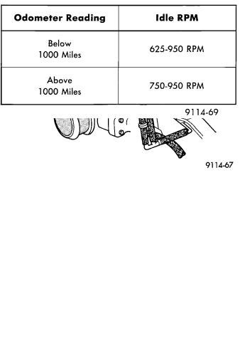
IDLE SPECIFICATIONS

Ä
If idle RPM is not within specification replace throttle body.
(13)Shut off engine.
(14)Remove Special Tool number 6457 from intake manifold PCV nipple. Reinstall the PCV valve hose.
(15)Remove DRBII.
(16)Reinstall air cleaner assembly. Reinstall heated air door vacuum hose.
(17)Disconnect timing check device and tachom-
eter.
THROTTLE BODY MINIMUM AIR FLOW CHECK PROCEDUREÐTURBO I ENGINES
(1)Warm engine in Park or neutral until the cooling fan has cycled on and off at least once.
(2)Hook-up timing check device and Tachometer.
(3)Disconnect the coolant temperature sensor and set basic timing to 12° BTDC 6 2° BTDC.
(4)Shut off engine. Connect harness connector to coolant temperature sensor.
(5)Disconnect the PCV valve hose from the nipple on the intake manifold.
(6)Attach Air Metering Fitting #6457 (0.125 in. orifice) to the intake manifold PCV nipple (Fig. 7).
(7)Disconnect 3/16 inch manifold vacuum purge line from the top of the throttle body. Cap the 3/16 inch throttle body nipple.
(8)Connect Diagnostic Readout Box II (DRB II).
(9)Restart engine. Allow engine to idle for at least one minute.
(10)Using the DRB II, access Min. Airflow Idle Spd. The following will then occur:
²AIS motor will fully close.
²Idle spark advance will become fixed.
²Engine RPM will be displayed on Diagnostic Readout Box II (DRB II).
(11)Check idle RPM with tachometer, if idle RPM is within the below specification then the throttle body minimum airflow is set correctly.
IDLE SPECIFICATIONS
If the idle RPM is not within specification, replace the throttle body.
(12) Shut off engine.
IGNITION SYSTEMS 8D - 17
(13)Remove Air Metering Fitting #6457 from the intake manifold PCV nipple. Reinstall the PCV valve hose.
(14)Remove DRB II.
(15)Disconnect timing check device and tachom-
eter.
(16)Reconnect purge line to throttle body.
THROTTLE BODY MINIMUM AIR FLOW CHECK PROCEDUREÐ3.0L ENGINE
(1)Warm engine in Park or Neutral until the cooling fan has cycled on and off at least once.
(2)Ensure that all accessories are off.
(3)Hook-up the timing check device and tachom-
eter.
(4)Disconnect the coolant temperature sensor and set basic timing to 12° BTDC 6 2° BTDC.
(5)Shut off engine. Reconnect coolant temperature sensor wire.
(6)Disconnect the PCV valve hose from the PCV valve (Fig. 8).
(7)Plug the PCV valve nipple.
Fig. 8 PCV ValveÐ3.0L Engine
(8)Disconnect the idle purge hose from the engine vacuum harness tee (Fig. 9).
(9)Install Air Metering Fitting #6457 (0.125 inch orifice) in the intake manifold mounted idle purge hose (Fig. 7).
(10)Connect Diagnostic Readout Box II (DRB II).
(11)Restart the engine, allow engine to idle for at least one minute.
(12)Using the DRBII, access Min. Airflow Idle
Speed.
(13)The following will then occur:
²AIS motor will fully close.
²Idle spark advance will become fixed.
²Engine RPM will be displayed on Diagnostic Readout Box II (DRB II)
(14)Check idle RPM with tachometer, if idle RPM is within the below specification then the throttle body min. air flow is set correctly.
8D - 18 IGNITION SYSTEMS |
|
Ä |
|
Fig. 9 Idle Purge HoseÐ3.0L
IDLE SPECIFICATIONS
(15) If idle RPM is not within specifications, shut off the engine and clean the throttle body as follows:
(a) Remove the throttle body from engine.
WARNING: CLEAN THROTTLE BODY IN A WELL VENTILATED AREA. WEAR RUBBER OF BUTYL GLOVES, DO NOT LET MOPAR PARTS CLEANER COME IN CONTACT WITH EYES OR SKIN. AVOID INGESTING THE CLEANER. WASH THOROUGHLY AFTER USING CLEANER.
(b)While holding the throttle open, spray the entire throttle body bore and the manifold side of the throttle plate with Mopar Parts Cleaner. Only use Mopar Parts Cleaner to clean the throttle body.
(c)Using a soft scuff pad, clean the top and bottom of throttle body bore and the edges and manifold side of the throttle blade. The edges of the throttle blade and portions of the throttle bore that are closest to the throttle blade when is closed, must be free of deposits.
(d)Use compressed air to dry the throttle body.
(e)Inspect throttle body for foreign material.
(f)Install throttle body on manifold.
(g) Repeat steps 1 through 14. If the minimum air flow is still not within specifications, the problem is not caused by the throttle body.
(16)Shut off engine.
(17)Remove Air Metering Fitting #6457 from the intake manifold idle purge hose. Reconnect the hose to the engine vacuum harness tee.
(18)Remove the plug from the PCV valve. Reconnect the PCV valve hose to the PCV valve.
(19)Disconnect the DRB II.
IGNITION TIMING PROCEDUREÐ2.2L TBI, 2.5L TBI, TURBO I, AND 3.0L ENGINES
WARNING: APPLY PARKING BRAKE AND/OR BLOCK WHEELS BEFORE PERFORMING SETTING IGNITION TIMING OR PERFORMING ANY TEST ON AN OPERATING ENGINE.
Proper ignition timing is required to obtain optimum engine performance. The distributor must be correctly indexed to provide correct initial ignition timing.
(1)Set the gearshift selector in park or neutral and apply the parking brake. All lights and accessories must be off.
(2)If using a magnetic timing light, insert the pickup probe into the open receptacle next to the timing scale window. If a magnetic timing unit is not available, use a conventional timing light connected to the number one cylinder spark plug cable.
Do not puncture cables, boots or nipples with test probes. Always use proper adapters. Puncturing the spark plug cables with a probe will damage the cables. The probe can separate the conductor and cause high resistance. In addition breaking the rubber insulation may permit secondary current to arc to ground.
(3)Turn selector switch to the appropriate cylinder position.
(4)Start engine and run until operating temperature is obtained.
(5)With the engine at normal operating temperature, connect the DRB II to the diagnostic connector. Access the State Display screen. Refer to the appropriate Powertrain Diagnostics Procedures Manual. If not using the DRB II tester, disconnect the coolant temperature sensor electrical connector.
The electric radiator fan will operate and the Check Engine light will turn on after disconnecting the coolant sensor or starting the DRB II procedure.
(6)Aim Timing Light at timing scale (Fig. 10 or Fig. 11) or read magnetic timing unit. If flash occurs when timing mark is before specified degree mark, timing is advanced. To adjust, turn distributor housing in direction of rotor rotation.
If flash occurs when timing mark is after specified degree mark, timing is retarded. To adjust, turn dis-