

8D - 28 IGNITION SYSTEMS |
|
Ä |
|
Fig. 6 Spark Plug Wire RoutingÐ3.3L and 3.8L En-
gines
condition. Nipples should fit tightly on the coil and distributor cap towers and spark plug cover should fit tight around spark plug insulators. Loose cable connections can cause ignition malfunctions by permitting water to enter the towers, corroding, and increasing resistance.
SPARK PLUGS
The Turbo III, 3.3L and 3.8L engines use resistor spark plugs. They have resistance values of 6,000 to 20,000 ohms when checked with at least a 1000 volt tester.
Remove the spark plugs and examine them for burned electrodes and fouled, cracked or broken porcelain insulators. Keep plugs arranged in the order in which they were removed from the engine. An isolated plug displaying an abnormal condition indicates that a problem exists in the corresponding cylinder. Replace spark plugs at the intervals recommended in Group O.
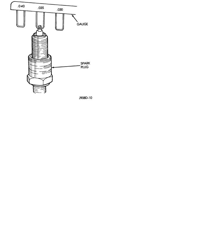
Spark plugs that have low milage may be cleaned and reused if not otherwise defective. Refer to the Spark Plug Condition section of this group. After cleaning, file the center electrode flat with a small point file or jewelers file. Adjust the gap between the electrodes (Fig. 8) to the dimensions specified in the chart at the end of this section.
Fig. 7 Single Board Engine Controller
SPARK PLUG CABLES
Spark Plug cables are sometimes referred to as secondary ignition wires. The wires transfer electrical current from the distributor to individual spark plugs at each cylinder. The spark plug cables are of nonmetallic construction and have a built in resistance. The cables provide suppression of radio frequency emissions from the ignition system.
Check the spark plug cable connections for good contact at the coil and distributor cap towers and at the spark plugs. Terminals should be fully seated. The nipples and spark plug covers should be in good
Fig. 8 Setting Spark Plug Electrode GapÐTypical
Always tighten spark plugs to the specified torque. Over tightening can cause distortion and change spark plug gap. Tighten Turbo III, 3.3L and 3.8L spark plugs to 28 NIm (20 ft. lbs.) torque.

Ä
SPARK PLUG CONDITION
NORMAL OPERATING CONDITIONS
The few deposits present will be probably light tan or slightly gray in color with most grades of commercial gasoline (Fig. 9). There will not be evidence of electrode burning. Gap growth will not average more than approximately 0.025 mm (.001 in) per 1600 km (1000 miles) of operation. Spark plugs that have normal wear can usually be cleaned, have the electrodes filed and regapped, and then reinstalled.
Fig. 9 Normal Operation and Cold (Carbon) Fouling
Some fuel refiners in several areas of the United States have introduced a manganese additive (MMT) for unleaded fuel. During combustion, fuel with MMT may coat the entire tip of the spark plug with a rust colored deposit. The rust color deposits can be misdiagnosed as being caused by coolant in the combustion chamber. Spark plug performance is not affected by MMT deposits.
COLD FOULING (CARBON FOULING)
Cold fouling is sometimes referred to as carbon fouling because the deposits that cause cold fouling are basically carbon (Fig. 9). A dry, black deposit on one or two plugs in a set may be caused by sticking valves or defective spark plug cables. Cold (carbon) fouling of the entire set may be caused by a clogged air cleaner.
Cold fouling is normal after short operating periods. The spark plugs do not reach a high enough operating temperature during short operating periods.
WET FOULING
A spark plug that is coated with excessive wet fuel or oil is wet fouled. In older engines, wet fouling can be caused by worn rings or excessive cylinder wear.
Break-in fouling of new engines may occur before normal oil control is achieved. In new or recently overhauled engines, wet fouled spark plugs can be usually be cleaned and reinstalled.
IGNITION SYSTEMS 8D - 29
OIL OR ASH ENCRUSTED
If one or more plugs are oil or oil ash encrusted, engine oil is entering the combustion chambers (Fig. 10). Evaluate the engine to determine the cause.
Fig. 10 Oil or Ash Encrusted
HIGH SPEED MISS
When replacing spark plugs because of a high speed miss condition; wide open throttle operation should be avoided for approximately 80 km (50 miles) after installation of new plugs. This will allow deposit shifting in the combustion chamber to take place gradually and avoid plug destroying splash fouling shortly after the plug change.
ELECTRODE GAP BRIDGING
Loose deposits in the combustion chamber can cause electrode gap bridging. The deposits accumulate on the spark plugs during continuous stop-and-go driving. When the engine is suddenly subjected to a high torque load, the deposits partially liquefy and bridge the gap between the electrodes (Fig. 11). This short circuits the electrodes. Spark plugs with electrode gap bridging can be cleaned using standard procedures.
SCAVENGER DEPOSITS
Fuel scavenger deposits may be either white or yellow (Fig. 12). They may appear to be harmful, but are a normal condition caused by chemical additives in certain fuels. These additives are designed to change the chemical nature of deposits and decrease spark plug misfire tendencies. Accumulation on the ground electrode and shell area may be heavy but the deposits are easily removed. Spark plugs with scavenger deposits can be considered normal in con-