

Ä |
|
COOLING SYSTEM 7 - 15 |
|
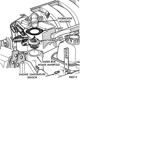
Fig. 11 Thermostat, Housing, and Water BoxÐ3.0L
Engine
Fig. 12 Thermostat InstalledÐ3.0L Engine
INSTALLATIONÐ3.3L AND 3.8L ENGINE
Place a new gasket (dipped in water) on the water box surface, center thermostat into opening in the intake manifold. Place housing over gasket and thermostat, making sure thermostat is in recess provided (Fig. 13). Bolt housing to intake manifold, tighten bolts to 28 NIm (250 in. lbs.). Refill cooling system (see Refilling System).
COOLANT
The cooling system is designed around the coolant. The coolant must accept heat from engine metal, in the cylinder head area near the exhaust valves. Then carry this heat to the radiator where the tube/fin assemblies of these components can give it up to the air.
Fig. 13 Thermostat, Housing and WaterboxÐ3.3L
and 3.8L Engine
PERFORMANCE
Performance is measurable. For heat transfer pure water excels (Formula = 1 btu per minute for each degree of temperature rise for each pound of water). This formula is altered when necessary additives to control boiling, freezing, and corrosion are added as follows:
²Pure Water (1 btu) boils at 100°C (212°F) and freezes at 0°C (32°F).
²100 Percent Glycol (.7 btu) can cause a hot engine and detonation and will raise the freeze point to 22°C (-8°F).
²50/50 Glycol and Water (.82 btu) is the recommended combination that provides a freeze point of -37°C(-35°F).The radiator, water pump, engine water jacket, radiator pressure cap, thermostat, temperature gauge, sending unit and heater are all designed for 50/50 glycol.
Where required, a 56 percent glycol and 44 percent water mixture will provide a freeze point of-59°C (-50°F).
CAUTION: Richer mixtures cannot be measured with field equipment which can lead to problems associated with 100 percent glycol.
SELECTION AND ADDITIVES
The use of aluminum cylinder heads, intake manifolds, and water pumps requires special corrosion protection. Mopar Antifreeze, Prestone II, Peak or antifreeze containing Alugard 340-2, or their equivalent are recommended for best engine cooling without corrosion. When mixed only to a freeze point of